BadgerHack: Gaming Add-On Kit
Contributors:
 Shawn Hymel
Shawn Hymel 
Hardware Hookup
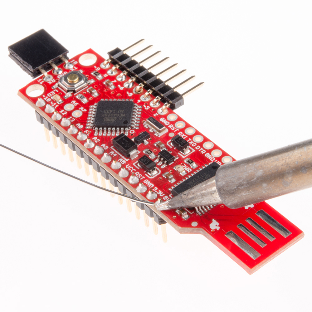
To begin, snap off 15 pins from the break-away headers, and solder them to the through-holes on the side opposite the LED array of the BadgerStick.
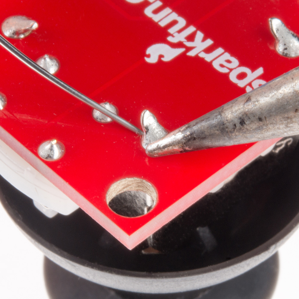
Solder the Thumb Joystick to the Thumb Joystick Breakout board.
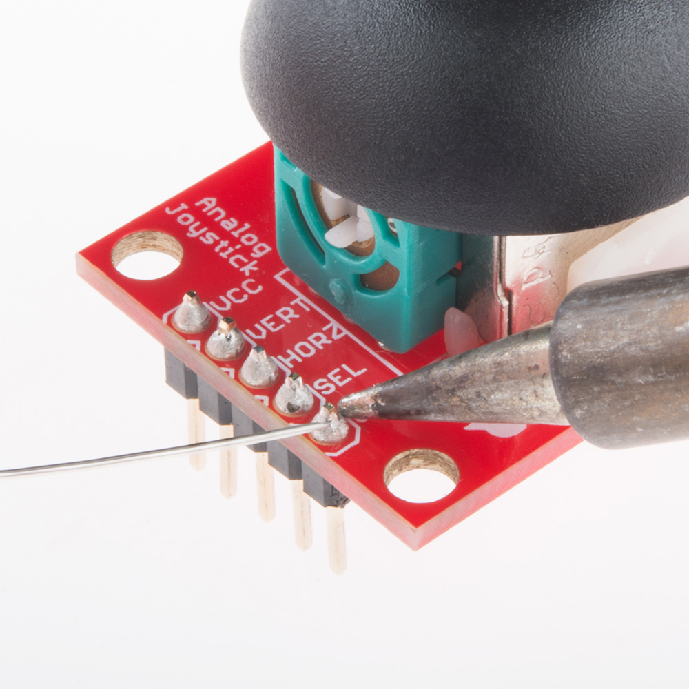
Snap off 5 pins from the break-away headers, and solder them to the through-holes on the Joystick Breakout Board.
Connections
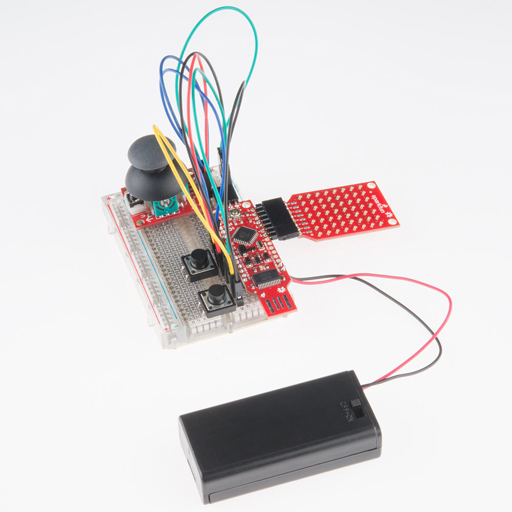
Place the BadgerStick in the breadboard with pin 10 in position i13 and pin 5V in position i27.
Connect the rest of the components as follows:
| Component | Breadboard | |||
|---|---|---|---|---|
| Thumb Joystick Breakout* | i7 (VCC) | i6 (VERT) | i5 (HOR) | i3 (GND) |
| Pushbutton | c20 | c22 | f20 | f22 |
| Pushbutton | c28 | c30 | f28 | f30 |
| Jumper Wire | ( - ) | g30 | ||
| Jumper Wire | ( - ) | g25 | ||
| Jumper Wire | ( - ) | g22 | ||
| Jumper Wire | ( - ) | j3 | ||
| Jumper Wire | j7 | g23 | ||
| Jumper Wire | j6 | g18 | ||
| Jumper Wire | j5 | g17 | ||
| Jumper Wire | g21 | g28 | ||
* Pins not listed are not used.
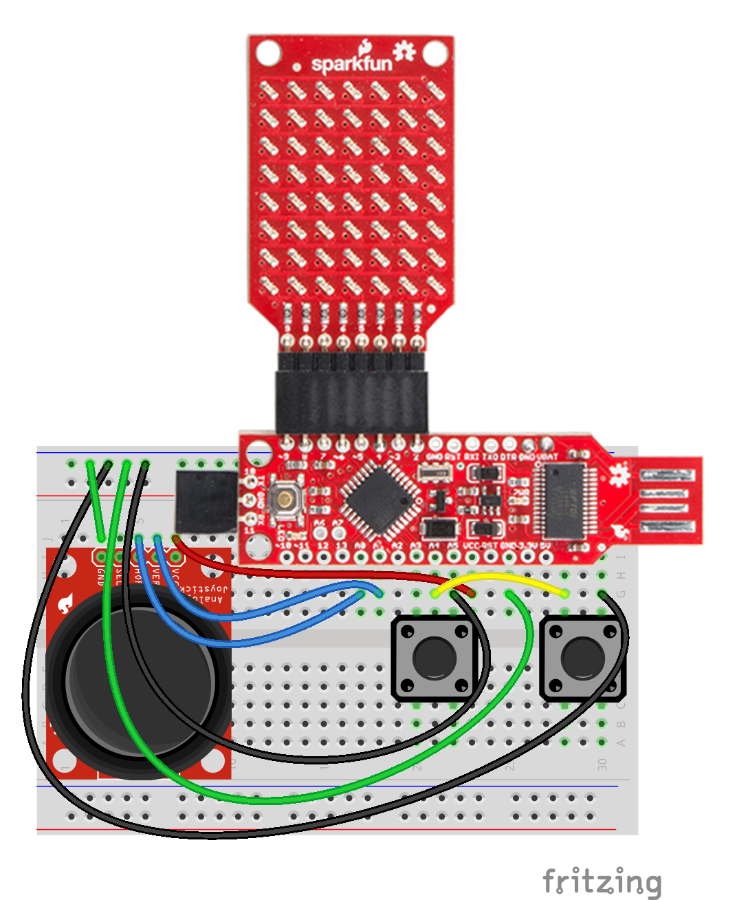
Wire colors correspond to the colors of the table above.
IMPORTANT: You can leave the battery pack soldered into the BadgerStick if you desire. If you remove the battery pack, you will need to supply power through another means, such as a USB port or a USB extension cable.
You should now have a makeshift game controller with a tiny LED screen!