Force Sensitive Resistor Hookup Guide
 jimblom,
  bboyho
Example Hardware Hookup
By creating a voltage divider with the FSR and another resistor, you can create a variable voltage output, which can be read by a microcontroller’s ADC input.
Selecting a Static Resistor
The tricky part of voltage-dividing an FSR is selecting a static resistor value to pair with it. You don't want to overpower the maximum resistance of the FSR, but you also don't want the FSR's minimum resistance to be completely overshadowed either.
It helps to know what range of force you'll be reading. If your project's force-sensing covers the broad range of the FSR (e.g. 0.1-10kg), try to pick a static resistance in the middle-range of the FSR's resistive output -- something in the middle of 200-6kΩ. 3kΩ, or a common resistor like 3.3kΩ, is a good place to start.
Short on Resistors? If all you have is 10kΩ resistors (looking at you Sensor Kit visitors), you can still make something close to 3k! Try putting three 10kΩ's in parallel to create a 3.33kΩ monster resistor. Or put three 330Ω resistors in series to create a 990Ω concoction, which will work pretty well too.
Example Circuit
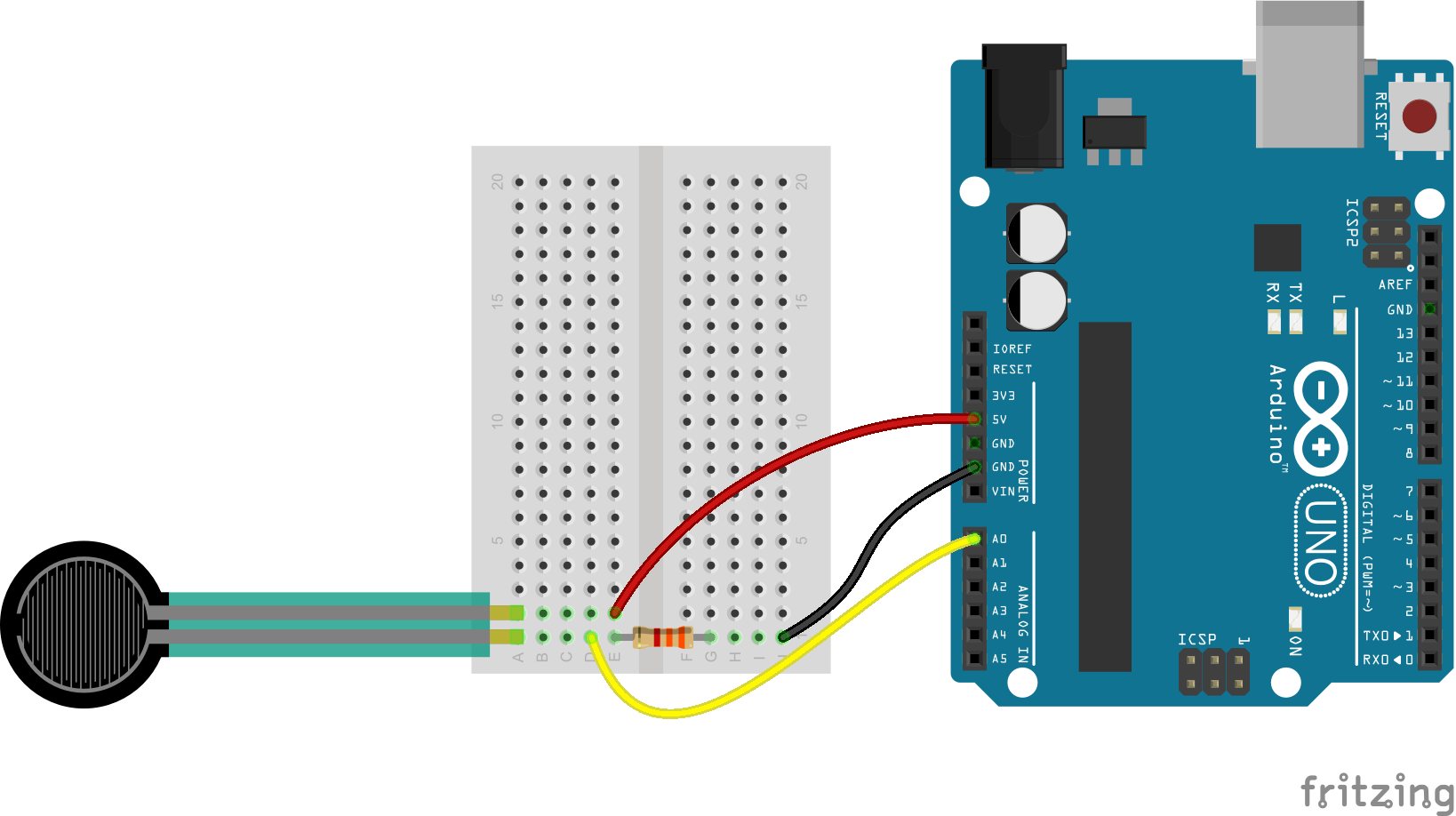
Here's a Fritzing diagram combining the Interlink FSR, 3.3kΩ resistor, three jumper wires and the Arduino. The circuit will be the same for TekScan. You'll just need to adjust the resistor value accordingly.
And the schematic:

This voltage divider will cause the voltage at A0 to increase as the resistance of the FSR decreases. When the FSR is left untouched, measuring as nearly an open circuit, the voltage at A0 should be zero. If you press as hard as possible on the FSR, the voltage should increase close 5V.