How to Make a Custom EL Wire Extension Cable
 bboyho
Hardware Assembly
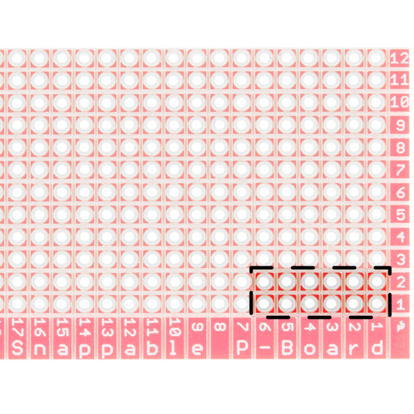
First, break off a 2x6 grid of plated through holes from the snappable protoboard.
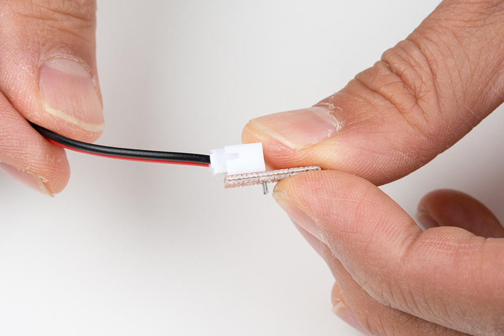
Insert the JST connector connected to the jumper wire assembly such that the socket's end is flush with the board. This should be 3x plated through holes into the grid.
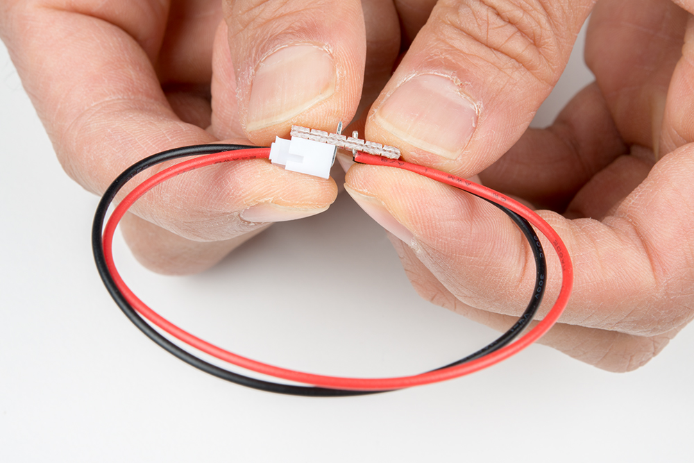
Loop the wire around and insert the tinned wires on the opposite end so that they are adjacent to the JST connector's pins. To be consistent, connect the red wire's terminals together. Repeat for the black wire. Leave some room with 4x through holes at the end of the protoboard to reinforce the wire connection and provide some strain relief.
Add a solder jumper between the pin and wire for the red wire. Repeat for the black wire. When finished, remove the JST connector from the socket.

Remember, EL wire runs on AC power. It’s important to mention that the AC power coming from the inverter is not enough to hurt or kill you. However, it is enough to give you a good shock so it is a good idea to insulate the connection. Start by wrapping a piece of electrical tape around the middle of the JST connector's socket.
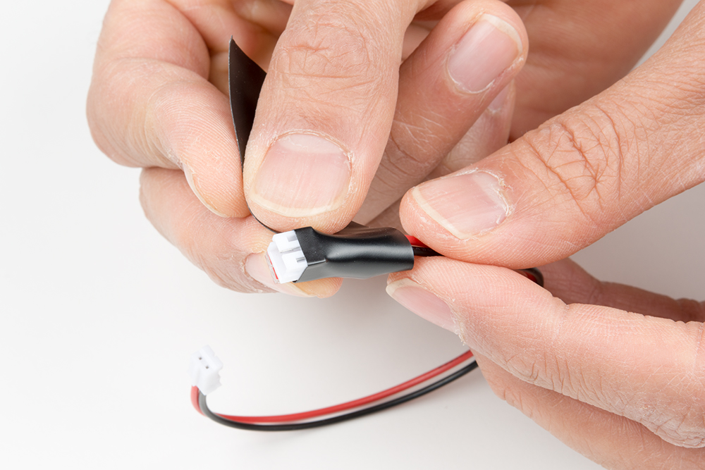
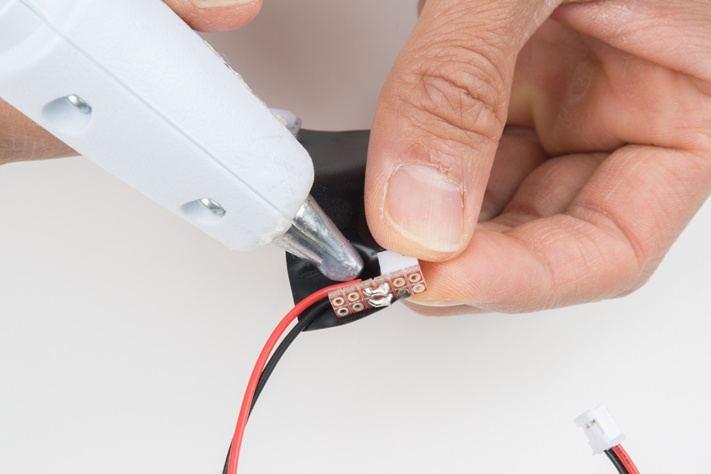
Add a drop of hot glue in the middle to secure the piece of tape and connection further. Make sure to not get any hot glue inside the JST connector's socket.
Finish wrapping the remaining electrical tape around the cable. The electrical tape will become tapered as you move away from the JST connector.
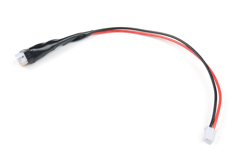
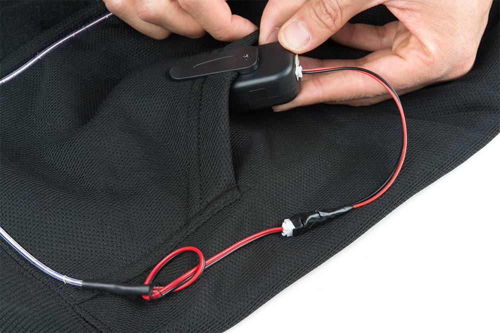
Add the extension cable between the inverter and EL wire. In the image below, the EL Wire extension cable provided easy access to the EL inverter battery pack from a hoodie's pocket.