Motion Controlled Wearable LED Dance Harness
 bboyho
Hardware Hookup
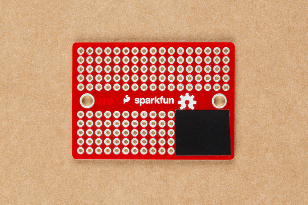
When soldering the n-channel MOSFET to the solderable breadboard, a piece of electrical tape was added to the exposed drain on the back of the MOSFET. While it was not necessary, it was a reminder to not solder any circuits under the exposed drain where it could make contact via the plated through holes.
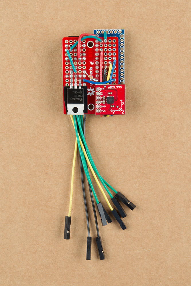
If you have not already, solder straight male headers on your Arduino Pro Mini 3.3V/8MHz. Also, make sure to solder straight headers to your ADXL335 accelerometer. Then solder the pieces together on the solderable breadboard and create the same connections with stripped wire as explained earlier. Wires terminated with a female header were used to connect to the LED strip's male headers. There are a lot of connections that need to be soldered so we'll just skip ahead to the completed circuit. Your circuit will look similar to the images below.
 |
 |
| Front View | Back View |