SparkFun Arduino ProtoShield Hookup Guide
 bboyho
Example Code
Note: The following examples assumes you are using the latest version of the Arduino IDE on your desktop. If this is your first time using Arduino, please review our tutorial on installing the Arduino IDE.
Blinking LED
Let's connect L1 to pin 13 using a wire. Assuming that you soldered to L1, connect it to pin 13.
| Prototyping Hardware | Arduino |
|---|---|
| L1 | 13 |
Copy the code below and upload to your Arduino!
language:c
/*BLINKING AN LED

  Turn an LED on for one second, off for one second,
  and repeat forever.

  This sketch was written by SparkFun Electronics,
  with lots of help from the Arduino community.
  This example is based on the blinking an LED
  example in the SparkFun Inventor's Kit v3.3.

  This code is completely free for any use.
  Visit https://learn.sparkfun.com/tutorials/sik-experiment-guide-for-arduino---v33/experiment-1-blinking-an-led
  for more information.
  Visit http://www.arduino.cc to learn about the Arduino.

  Version 2.0 6/2012 MDG
******************************************************************************/


// The LED is connected to digital pin 13
// Change the pin number depending on
// what L1 is connected to.
const int L1 = 13;

void setup()
{
  pinMode(L1, OUTPUT);  //Set L1 to output
}

void loop()
{
  digitalWrite(L1, HIGH);   // Turn on the LED
  delay(1000);                     // Wait for one second
  digitalWrite(L1, LOW);    // Turn off the LED
  delay(1000);                     // Wait for one second
}
LED labeled as L1 should begin blinking.
Fading LED
Let's connect L2 to pin 6 and to fade in and out. Assuming that you soldered to L2, connect it to pin 6.
| Prototyping Hardware | Arduino |
|---|---|
| L2 | 6 |
Copy the code below and upload to your Arduino!
language:c
/* Fading LED

  Use for-loops to smoothly vary the brightness of an LED

  This sketch was written by SparkFun Electronics,
  with lots of help from the Arduino community.
  This example is based on the Fading LEDs example
  in the LilyPad Development Board Activity Guide.

  This code is completely free for any use.
  Visit https://learn.sparkfun.com/tutorials/lilypad-development-board-activity-guide/4-fading-leds
  for more information
  Visit http://www.arduino.cc to learn about the Arduino.

******************************************************************************/

// Create integer variable for the LED pin we'll be using:
const int L2 = 6;

// Create a new integer variable called brightness:
int brightness;

void setup()
{
  // Set the LED pins to be output:
  pinMode(L2, OUTPUT);
}

void loop()
{
  // The two "for loops" below will make a LED fade on and off in a "breathing" pattern.

  // Now we'll have the program automatically change the value of brightness
  // using a command called "for".

  // for is like a tiny version of loop. The for command has several parts:
  // 1. something to do before starting (brightness = 0)
  // 2. a test to decide whether to keep going (brightness <= 255)
  // 3. a block of commands to run (everything within the {} below the for)
  // 4. a command to run before doing it again (brightness = brightness + 1)

  // Here's a for command which will start brightness at 0, check to see if it's less than
  // or equal to 255, run the commands after it, then add one to brightness and start over:

  for (brightness = 0; brightness <= 255; brightness = brightness + 1)
  {
    // Within the loop, we'll use brightness variable to control the brightness of the LEDs:

    analogWrite(L2, brightness);

    // NOTE that not all pins work with analogWrite!
    // The ones with a "~" in front of them will change brightness,
    // the others will only turn on if brightness > 128.
    // Both types are used above, run the code and note the difference between them.

    // The delay command controls the speed - if you make the delay larger,
    // it will slow down the loop. Smaller, and it will run faster:

    delay(5);
  }

  // What if we want the LED to start at full brightness and fade to black?
  // We can easily set up the for loop to run in reverse:

  for (brightness = 255; brightness >= 0; brightness = brightness - 1)
  {
    analogWrite(L2, brightness);
    delay(5);
  }
}
LED labeled as L2 should begin fading in and out. Try connecting and redifining the LED to another pin on your Arduino to see if you can still fade.
Momentary Push Button
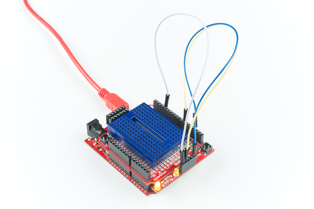
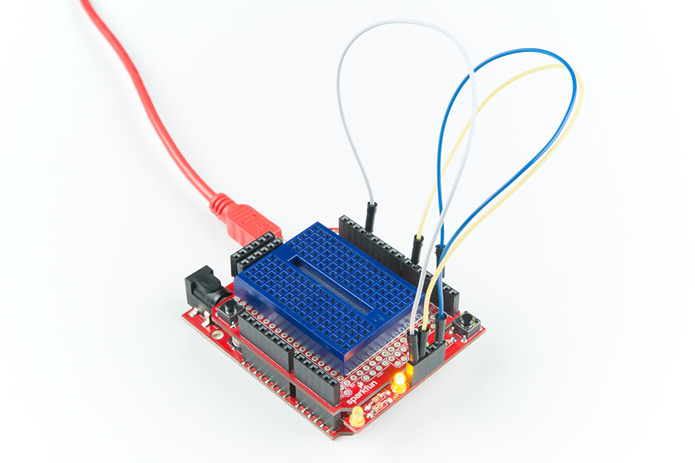
Let's connect SW2 to pin 2 to read a push button. For feedback, we will be using both of the LEDs in our prototyping hardware. Assuming that you soldered to SW2, L2, and L1, connect it to their respective pins on 2, 6, and 13.
| Prototyping Hardware | Arduino |
|---|---|
| SW2 | 2 |
| L2 | 6 |
| L1 | 13 |
Copy the code below and upload to your Arduino!
language:c
/*Momentary Push Button

  Use momentary pushbuttons for digital input

  This sketch was written by SparkFun Electronics,
  with lots of help from the Arduino community.
  This example is based on the push button
  example in the SparkFun Inventor's Kit v3.3

  This code is completely free for any use.
  Visit https://learn.sparkfun.com/tutorials/sik-experiment-guide-for-arduino---v33/experiment-5-push-buttons
  for more information.
  Visit http://www.arduino.cc to learn about the Arduino.

  Version 2.0 6/2012 MDG
  Version 2.1 9/2014 BCH
****************************************************************/

const int SW2 = 2;  // pushbutton 1 pin
const int L1 =  13;    // LED pin
const int L2 =  6;     // LED pin

int button1State;  // variables to hold the pushbutton states

void setup()
{
  // Set up the pushbutton pins to be an input:
  pinMode(SW2, INPUT);
  // Set up the LED pin to be an output:
  pinMode(L1, OUTPUT);
  pinMode(L2, OUTPUT);
}

void loop()
{
  button1State = digitalRead(SW2);

  // if SW2 is pressed
  if (button1State == LOW) {
    digitalWrite(L1, HIGH);  // turn the LED on
    digitalWrite(L2, HIGH);  // turn the LED on
  }
  else {
    digitalWrite(L1, LOW);  // turn the LED off
    digitalWrite(L2, LOW);  // turn the LED off
  }
}
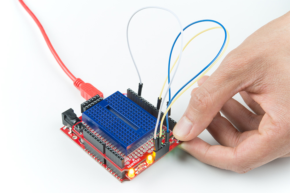
Pressing on the button should light up both LEDs simultaneously. Removing your finger from the button should turn them off.
Bluetooth Serial Passthrough
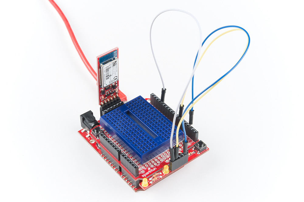
Let's try to send a character between two BlueSMiRF Silvers (i.e. the RN42s). In this example, we will need two bluetooths, ProtoShields, and Arduinos. Assuming that the boards are soldered, connect the BlueSMiRFs to the Software Serial UART port. We will be using the default connection to software serial pins 10 and 11. Simply align the silkscreen as indicated in the hookup table below.
| BlueSMiRF Silver | ProtoShield Software Serial UART port |
|---|---|
| RX-I | RXI (D11) |
| TX-O | TXO (D10) |
| GND | GND (GND) |
| VCC | VCC (5V) |
We will also be using the same connection to the prototyping hardware.
| Prototyping Hardware | Arduino |
|---|---|
| SW2 | 2 |
| L2 | 6 |
| L1 | 13 |
Power both up, copy the code below, and upload to both Arduinos!
language:c
/*
  Example Bluetooth Serial Passthrough Sketch
  modified by: Ho Yun "Bobby" Chan
  date: May 17, 2018
  by: Jim Lindblom
  date: February 26, 2013
  SparkFun Electronics
  license: Public domain

  This example sketch converts an RN-42 bluetooth module to
  communicate at 9600 bps (from 115200), and passes any serial
  data between Serial Monitor and bluetooth module.
****************************************************************/

#include <SoftwareSerial.h>

int bluetoothTx = 10;  // TX-O pin of bluetooth mate, Arduino D10
int bluetoothRx = 11;  // RX-I pin of bluetooth mate, Arduino D11

SoftwareSerial bluetooth(bluetoothTx, bluetoothRx);// (Arduino SS_RX = pin 10, Arduino SS_TX = pin 11)

void setup()
{
  Serial.begin(9600);  // Begin the serial monitor at 9600bps

  bluetooth.begin(115200);  // The Bluetooth Mate defaults to 115200bps
  bluetooth.print("$");  // Print three times individually
  bluetooth.print("$");
  bluetooth.print("$");  // Enter command mode
  delay(100);  // Short delay, wait for the Mate to send back CMD
  bluetooth.println("U,9600,N");  // Temporarily Change the baudrate to 9600, no parity
  // 115200 can be too fast at times for NewSoftSerial to relay the data reliably
  bluetooth.begin(9600);  // Start bluetooth serial at 9600
}

void loop()
{
  if (bluetooth.available()) // If the bluetooth sent any characters
  {
    // Send any characters the bluetooth prints to the serial monitor
    Serial.print((char)bluetooth.read());
  }
  if (Serial.available()) // If stuff was typed in the serial monitor
  {
    // Send any characters the Serial monitor prints to the bluetooth
    bluetooth.print((char)Serial.read());
  }
  // and loop forever and ever!
}
Discovering, Pair, and Autoconnecting Bluetooths
Once uploaded,
- open the Arduino Serial Monitor set at 9600 baud with No line ending
- send $$$ and hit the Send button to set the bluetooth in command mode
- change the Arduino Serial Monitor from No Line Ending to Newline
- send the autoconnect command sm,3
- send the inquiry scan command i to scan for the other bluetooth in range
You should see something similar to the output below.
language:bash
CMD
AOK
Inquiry, COD=0
Found 1
000666643FBF,RN42-3FBF,1F00
Inquiry Done
The other RN42 bluetooth that was in range came up with address of 000666643FBF. You should see something similar when connecting a RN-41 or RN-42. Type the following command and change the address to the one that you obtained:
- c,000666643FBF and hit the Send button
This will pair and connect both bluetooths together. The address will be saved in memory and auto connect every time there is a power cycle. Open a serial terminal (since you can only have one Arduino Serial Monitor open at a time) set at 9600 baud and connect the other Arduino/ProtoShield/BlueSMiRF. Sending any character from the Arduino Serial Monitor should pop up on the serial terminal and vice versa!
Combining It All to Send a Message!
Let's send a simple message between the two bluetooths now that they are configured to autoconnect. Copy the code below, and upload to both Arduinos!
language:c
/*
  Example Serial Bluetooth Messenger
  by: Ho Yun "Bobby" Chan
  SparkFun Electronics
  date: May 16, 2018
  license: Public domain

  This example sketch converts an RN-42 bluetooth module to
  communicate at 9600 bps (from 115200). Assuming that the
  two bluetooths are paired and configured to autoconnect,
  a message is sent with the push of a button. Any
  received characters from the other bluetooth will display
  on the serial monitor.

  This sketch was written by SparkFun Electronics.
  This example is based on the Example Bluetooth Serial
  Passthrough Sketch by Jim Lindblom.

  This code is completely free for any use.
  Visit https://learn.sparkfun.com/tutorials/using-the-bluesmirf
  for more information.
****************************************************************/

#include <SoftwareSerial.h>

const int SW2 = 2;  // pushbutton 1 pin
const int L1 =  13;    // LED pin for push button
const int L2 =  6;     // LED pin for received character

int button1State;  // variables to hold the pushbutton states

int bluetoothTx = 10;  // TX-O pin of bluetooth mate, Arduino D10
int bluetoothRx = 11;  // RX-I pin of bluetooth mate, Arduino D11

SoftwareSerial bluetooth(bluetoothTx, bluetoothRx);// (Arduino SS_RX = pin 10, Arduino SS_TX = pin 11)

void setup()
{
  // Set up the pushbutton pins to be an input:
  pinMode(SW2, INPUT);
  // Set up the LED pin to be an output:
  pinMode(L1, OUTPUT);
  pinMode(L2, OUTPUT);

  Serial.begin(9600);  // Begin the serial monitor at 9600bps

  bluetooth.begin(115200);  // The Bluetooth Mate defaults to 115200bps
  bluetooth.print("$");  // Print three times individually
  bluetooth.print("$");
  bluetooth.print("$");  // Enter command mode
  delay(100);  // Short delay, wait for the Mate to send back CMD
  bluetooth.println("U,9600,N");  // Temporarily Change the baudrate to 9600, no parity
  // 115200 can be too fast at times for NewSoftSerial to relay the data reliably
  bluetooth.begin(9600);  // Start bluetooth serial at 9600
}

void loop()
{
  button1State = digitalRead(SW2);

  //Send a character
  if (button1State == LOW) //if SW2 is pressed
  {
    // Send characters to bluetooth to transmit
    bluetooth.println("Hi!");
    digitalWrite(L1, HIGH);  // turn the LED on
  }
  else {
    digitalWrite(L1, LOW);  // turn the LED off
  }

  // If the bluetooth received any characters, print to the serial monitor
  if (bluetooth.available())
  {
    // Send any characters the bluetooth prints to the serial monitor
    Serial.print((char)bluetooth.read());
    digitalWrite(L2, HIGH);  // turn the LED on
  }
  else {
    digitalWrite(L2, LOW);  // turn the LED on
  }
  // and loop forever and ever!
}
Pressing a button on one of the Arduinos (as indicated by the blue mini-breadboard) should send a message and light up the LED labeled as L1 on the transmitting node. The receiving node (as indicated by the green mini-breadboard) will light up the LED labeled as L2 and print a message (in this case "Hi!") to a serial monitor or serial terminal. The other Arduino will to the same when you press on its button.
