Vernier Shield Hookup Guide
 bri_huang
Storing Data to an SD Card
What you'll need
Recommended Reading / Useful Resources
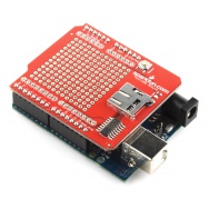
Adding an SD Card Interface to your Vernier shield is pretty simple. The SD Card shield will have to go below the Vernier Shield using a set of stack-able headers.
Upload this code to your shield. It logs raw voltage values of the sensors to a microSD Card, if you are using the SparkFun microSD Card Shield. If you are using your own SD Card shield implementation, double check the pin assignments for chipselect. On the SparkFun microSD Card Shield, chipselect is on pin 8.
This code example will read raw voltage levels from any analog Vernier Sensor that provides a voltage from 0 to 5V (this accounts for a majority of their sensors). Pressing the button (D12) will start the data collection for a time period defined by the variable duration. Data is logged to a file called "datalog.txt" and displayed to the Serial Monitor.
Upload the VernierSDStore sketch to your Arduino.
language:c
    /*
VernierShieldSDStore (v 2014.02)
Takes data from a Vernier Motion Detector connected to BTA connector.

The data is displayed to the serial monitor and saved to a file called datalog.txt

Data is currently displayed and stored as raw voltage levels from 0 to 5V. Currently working
integrate the AutoIDAnalog.ino code into this code so that data is automatically
calibrated.

Only the 5V analog signal is currently being used, but you can change the code to


See www.vernier.com/arduino for more information.
*/

#include <SD.h>      // includes the Arduino SD Library

// pin configurations for SparkFun Vernier Shield
// A1 = Analog 1
// A2 = Analog 2
#define A1_5V 0
#define A1_10V 1
#define A2_5V 2
#define A2_10V 3

char * filename = "datalog.txt";  /* sets the filename for data - change this
 if you want to use a different file name
 data will be concatenated onto the existing
 file if it exists */
float dataRate = 20.0;     // # of samples per second.
int duration = 5000;       // set the data collection duration in milliseconds
// default value is set to 5 seconds or 5000 milliseconds

unsigned long timeRef;      // reference for starting time
unsigned long timeInterval;
unsigned long elapsedTime;
unsigned long ndx = 0;

const int buttonPin = 12;   // digital button on Vernier Shield - used to start data collect
const int ledPin = 13;      // LED pin on Vernier Shield

/* Global Variable declarations for SD Card Shield */
const int chipSelect = 8;
File dataFile;

// variables used with VernierAnalogAutoID
//
int muxLSB = 10; //low byte of multiplexer
int muxMSB = 11; //high byte of multiplexer

int SensorRaw[2];
float SensorVoltage[2];
float VCC = 5.0;

void setup()
{
  // initialize serial communication at 9600 bits per second:
  Serial.begin(9600);

  // set the timeInterval based on dataRate
  timeInterval = 1E3 / dataRate;

  // initialize the buttonPin as an INPUT with a pull-up resistor
  pinMode(buttonPin, INPUT_PULLUP);
  pinMode(muxLSB, OUTPUT);
  pinMode(muxMSB, OUTPUT);

  Serial.println("*************************************************");
  Serial.println("Push button (D12) to start data collection.");
  Serial.println("Use reset button to reset / stop data collection.");
  Serial.println("*************************************************");

  while(digitalRead(buttonPin) == HIGH)
  {
    // holding loop until the button goes low.
  }

  /***********************
   * / Setup SD Card
  /***********************/
  pinMode(chipSelect, OUTPUT);

  Serial.print("Initializing SD card...");

  // see if the card is present and can be initialized:
  if (!SD.begin(chipSelect))
  {
    Serial.println("Card failed, or not present");
    // don't do anything more:
    return;
  }
  Serial.println("card initialized.");

  Serial.println();

  /***********************
   * / Print data header
  /***********************/
  Serial.println(" ");
  Serial.println("Vernier Format 2");
  Serial.println("Raw Readings taken using Ardunio");
  Serial.println("Data Set");
  Serial.print("Time");

  Serial.print("\t"); //tab character
  Serial.print ("Chan1");
  Serial.print("\t"); //tab character
  Serial.print("Chan2");


  Serial.println("");
  Serial.print("seconds");

  Serial.print("\t"); //tab character
  Serial.print ("V");
  Serial.print("\t"); //tab character
  Serial.print ("V");
  Serial.println();

  /*************************
   * / Print header to SD Card
  /*************************/

  dataFile = SD.open(filename, FILE_WRITE);
  if (dataFile) // if it opens sucessfully
  {
    dataFile.println("Vernier Format 2");
    dataFile.println("Raw Readings taken using Ardunio");
    dataFile.println("Data Set");
    dataFile.print("Time");
    // query the channel numbers

    // print sensor name -- data will be displayed in raw and voltage
    dataFile.print("\t"); //tab character
    dataFile.print("Chan1");
    dataFile.print("\t"); //tab character
    dataFile.print("Chan2");
    dataFile.println();

    // display the units
    dataFile.print("seconds");

    dataFile.print("\t");
    dataFile.print("V");
    dataFile.print("\t");
    dataFile.print("V");

    dataFile.close(); // close the datafile
  }
  else  // if(datafile) -- error opening SD card
  {
    Serial.println("error opening file.");
    Serial.println();
  }

  digitalWrite(ledPin, HIGH);
  timeRef = millis();
  ndx = 0;   // datapoint index
} // end setup

void loop()
{
  unsigned long currTime = millis();  // record current Time
  if ((currTime - timeRef) <= (duration))     // controls the duration of the data collection
  {
    if (currTime >= ndx*timeInterval + timeRef)  // controls so only runs once per timeInterval
    {
      ndx++;
      digitalWrite(ledPin, LOW); // blink the LED off to show data being taken.

      // Read in sensor values
      SensorRaw[0] = analogRead(A1_5V);
      SensorRaw[1] = analogRead(A2_5V);

      // Convert to voltage values
      SensorVoltage[0] = SensorRaw[0]*VCC/1023.0;
      SensorVoltage[1] = SensorRaw[1]*VCC/1023.0;
/* // uncomment these lines of code to use the +/- 10V sensors
      SensorRaw[0] = analogRead(A1_10V);
      SensorRaw[1] = analogRead(A2_10V);

      // Convert to voltage values (20V range, -10V offset)
      SensorVoltage[0] = SensorRaw[0]*20.0/1023.0 - 10.0;
      SensorVoltage[1] = SensorRaw[1]*20.0/1023.0 - 10.0;

*/

      dataFile = SD.open(filename, FILE_WRITE);
      // if the file is available, write to it:
      if (dataFile)
      {
        dataFile.print((currTime - timeRef)/ 1E3, 3);  // 4 decimal places
        dataFile.print("\t");
        dataFile.println(SensorVoltage[0]);
        dataFile.print("\t");
        dataFile.println(SensorVoltage[1]);
        dataFile.close();
      }

      // if the file isn't open, pop up an error:
      else
      {
        Serial.println("Error opening file.");
      }
      // Serial print to the serial monitor
      Serial.print((currTime - timeRef) / 1E3, 3);
      Serial.print("\t"); // tab character
      Serial.print(SensorVoltage[0]);
      Serial.print("\t");
      Serial.print(SensorVoltage[1]);
      Serial.println();

      digitalWrite(ledPin, HIGH); // turn the LED back on to show data collection
      // duration is still running.
    }
  }
  else  // duration is complete -- wait and reset if button is pressed
  {
    digitalWrite(ledPin, LOW);    // turn off LED to show data collection is done.
    while(digitalRead(buttonPin) == HIGH)
    {
      // holding loop until the button goes low.
    }
    // reset counters and timeRef
    digitalWrite(ledPin, HIGH);
    ndx = 0;
    timeRef = millis();

  }
} // end of loop