- Home
- Product Categories
- Infrared
- Photo Interrupter - GP1A57HRJ00F

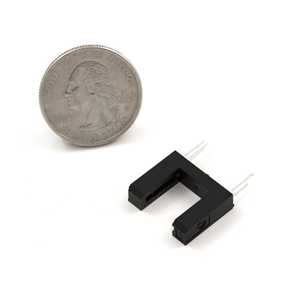
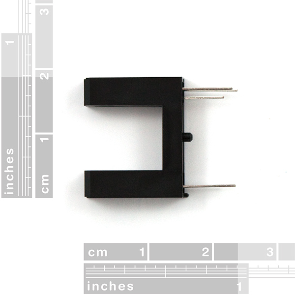
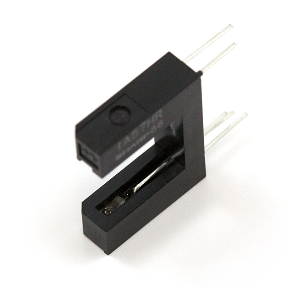
Photo interrupter, photogate, photodiode, phototransistor, whatever you want to call it, this sensor is composed of an infrared emitter on one upright and a shielded infrared detector on the other. By emitting a beam of infrared light from one upright to the other, the sensor can detect when an object passes between the uprights, breaking the beam. Used for many applications including optical limit switches, pellet dispensing, general object detection, etc. Gap width = 10mm
A breakout board is available.
Photo Interrupter - GP1A57HRJ00F Product Help and Resources
Resources and Going Further
Check out the GitHub repository for the example code:
Core Skill: Electrical Prototyping
If it requires power, you need to know how much, what all the pins do, and how to hook it up. You may need to reference datasheets, schematics, and know the ins and outs of electronics.
Skill Level: Rookie - You may be required to know a bit more about the component, such as orientation, or how to hook it up, in addition to power requirements. You will need to understand polarized components.
See all skill levels
Comments
Looking for answers to technical questions?
We welcome your comments and suggestions below. However, if you are looking for solutions to technical questions please see our Technical Assistance page.
Customer Reviews
4.8 out of 5
Based on 4 ratings:
3 of 3 found this helpful:
photo interrupter
Works absolutely fine. I am using it on a "persistence of vision" wheel to time the start of the display. The interruption lasts a fraction of a millisecond but triggers every time. I highly recommend buying the related circuit board. It makes mounting and use easier. I would also recommend that Sparkfun add mounting holes to the board. Current version has no screw holes.
1 of 1 found this helpful:
Works great; always keep some on hand; needs suggested interfacing
A photo-interrupter is so versatile, I'm keeping a couple in my kit of basics such as leds, 200ohm resistors, and buttons. Your list of uses could include detecting the initial position of stepper motors, detecting the position of DC motors, detecting doors opening, closing, or sliding open and closed, detecting a coin dropping through a slot, and on and on!
I soldered this part up to the suggested (almost required) Photo Interrupter Breakout Board - GP1A57HRJ00F, and it worked great with my Arduino Mega project.
My one wish is for better application circuit documentation. As things are, most people without EE degrees will have to buy the breakout board to use the part. I couldn't decipher the datasheet to work out a recommended wiring for Arduino.. A quick schematic sketch would be great.
So, I love this part when bought with the corresponding Breakout Board - it worked nearly the first time, and works over and over, and works for so many things. ...and thanks for making the Breakout Board; it's a lifesaver.
Very Good
They are very easy to use and work very will.
Needed to use 2N2222A NPN transistor to get enough current for LED
I tried driving a green LED directly off of the output and it lit but was really dim. There is an internal voltage regulator which also seems to limit the output current as well. I tried supplying 6V and 7.5V to the receiver end within the specified range. In either case, it output about 4.5 volts. And changing the series resistor with the LED from 220 ohm to 100 ohm to 0 ohm didn't change the brightness at all. Same thing with red (green LEDs need higher voltage difference than red). Measuring the resistance between VCC and VO gave about 13.5 kohms, which is less than the 15 kohms internal resistance specified in the data sheet. But that shouldn't make any significant difference in driving the LED. Finally I added a 2N2222A NPN transistor to the output by connecting the base to VO. Used a 220 ohm resistor in series with the green LED between emitter and ground. Put the power supply to 6 V and used a 1N4004 diode to safeguard the electrical power supply (reducing VCC to about 5.4 V) and used that to power both the photointerrupter and the 2N2222A transistor powering the LED. Bright as I wanted it to be. So my conclusion is that the output is mostly regulating the voltage and is somehow current limited. But it's internal to the device, so you cannot change it.
How small of a object can this detect?
Be VERY careful about voltage reversal! I cooked 4 of these (immediate poof of smoke when power applied) before i realized that the datasheet physical drawing shows the pins when the sensor is upside down. Thank god i ordered 5. Running straight off Arduino Uno and used a 330ohm resistor for the transmitter and getting nice response so far.
Would be nice on the next version if the components were a bit more tolerant. I'd pay an extra $.50 for that peace of mind.
is it running from 5V on arduino?
Before I ruin this, how many volts should it have, and how can I tell from the datasheet? I don't wish to destroy my last IR piece. Already burned out two IR leds. So, how many volts can each side take, maximum?
The emitter is the only one that you should worry about with powering. That one is a very sensitive little IR emitter. If you look at Figure 4 in the datasheet, you can see the curves for forward Voltage vs forward Current. You can see there that changing between 1V and 2V incurs a change between '1'mA and 300mA - well into the range where it would fry.
Rather than driving it by voltage, you should drive it by current. There's a couple of figures in the datasheet (some of which - test condition at 7mA - make me wonder if they typo'd something), but if you scroll down to page 7, you can see SHARP's design recommendations which state that forward current should be between 10mA and 20mA. So in your design you should try to make a 'constant' current regulation for 15mA. This can typically be done using just a resistor. Going back to figure 4, for 15mA the forward voltage at room temperature is - guesstimating - about 1.13V. (That iffy part of the datasheet lists 1.14V, so at least that's a bit of confirmation). After that you can use any normal LED calculator to find an appropriate resistor for your given supply voltage. SparkFun's breakout board for this component for use with an Arduino 5V uses a 220Ω resistor, but notes that 330Ω works as well. That would fit with my calculation (ends up at 270Ω) as well.
The detector side is much more forgiving, taking anywhere between 4.5 and 17V according to the datasheet. In SparkFun's breakout board, this means it's just hooked up directly with the detection pin going out to - in their case - one of the input pins on an Arduino. Note that most of the test conditions on the detector side are at 5V, and I certainly wouldn't actually drop 17V on it :)
Hopefully this should keep the other one from burning out on you - make sure you check all the connections, have a peek at that breakout board too :)
Snapping the alignment pin off the bottom of this thing is very easy and is required if you want a flush fit against the SparkFun breakout board.
We'll take that into consideration next revision. Thanks for the heads up.
Can anyone clarify the part's lifespan? Page 7 of the data sheet has a paragraph labeled "Degradation", that suggests to me that in continuously-powered applications the part may perform worse after a few years.
I'm building a lunar clock project that, if all goes well, will sit, powered, on a mantel for years.
Thinking about that, I think I want to power the detector only when I'm looking for the signal - e.g., connecting the IR LED power to an Arduino output pin rather than simply connecting it to 5V.
Any thoughts/insights? Thanks, Brad
Can the gap width be changed?
Note that one can also use a pair of high brightness LEDs. Use one as the Tx and the other as Rx. Connect the Rx to a CMOS invertor biassed as an amplifier and Bob's your uncle. The advantage is that it is visible - the disadvantage is also that it is visible - depends on what you are doing with it!
I looked at the spec sheet and did not see any data regarding how sensitive the detector is - i.e., how much light intensity is needed to cause output transistor to turn on.
I wanted to use one of these on a radon mitigation system's u-tube manometer*. If the fan stopped working, the colored liquid would rise, reducing the intensity of the light received and - I hope - triggering an alarm.
Does anyone know how much reduction in light transmission is needed to switch output from On to Off?
When I ordered this the datasheet link was working but now it appears it is not. Thanks.
does anyone know, the maximum sampling rate of those?? i would like to use it, to count "Gaps " in a rotating wheel... the wheel would rotate with about 4000rpm, and would have 36 gaps ,, per revolution.... would this sensor work??
Well, the datasheet says there is a 9uS Low-high propagation delay, and 15uS High-low propagation delay.
If you add them together you get 24uS, or a frequency of 41.67 KHz.
36 gaps per revolution gives you 0.6 (36/60) Hz for every RPM.
So assuming your micro is fast enough, this could, in theory, work all the way up to ~70,000 RPM, but don't expect great accuracy at those speeds (read below)
If you need very high accuracy, it actually won't work. For example, the Arduino's micros() function has 8uS resolution. So let's say you have 400 uS between 2 detected gaps. In that case, your code should convert that to 4167 RPM. However at 392 uS/gap, you'd get 4252 RPM; or at 408 uS/gap, 4085 RPM, both of which are probably huge differences, depending on what you're planning on using this for.
Does anyone know if these pins fit into a standard breadboard or perfboard?
Don't quite fit in a breadboard, but spread them apart a little, and they'll fit just fine.
I'm pretty novice about all this - but it isn't clear to me how much voltage to pump through this part. The datasheet says 5v output, but input goes all the way up to 17v? Does this thing regulate voltage by itself?
The input is a mere LED (okay, technically an IRED). Just put a resistor in series with it. For a 5V supply, a 330 ohm resistor should be fine.
Turns out datasheets tell a lot - by the look of the schematic, it does in fact have a regulator internally.
So... the V0 pin is useless, right? The middle one on the detector, pin 4 on the diagram?
That's Vo, I believe - the output pin. Not exactly useless ;)
See also: Photo Interrupter GP1A57HRJ00F Breakout Board and forum: amateur in trouble with GP1A57HRJ00F photo interrupter
Had to cut them half to widen the gap to almost 20mm. Still worked pretty well.
Before I go chop mine apart, I'm wondering if there is any connection between the two "arms" of this thing? I'd like to cut it in half in the middle and custom-mount the light and detector in a different housing. Anyone done that?
Also, any thoughts on how far apart this thing can be and still detect?
I just got round to using this with the sparkFun breakout board.
my issue is that it doesn't seem to be sensitive enough.
I'm trying to detect a drop of liquid falling and it doesn't want to trigger the sensor.
Is there any way to increase the sensitivity, I used a 220 ohm resistor on the board and am wondering if a different value would help me.
Any ideas?
Cheers.
Phil
I think your issue is due to the light passing through the liquid (and not tripping the sensor). I've been able to detect small objects moving at about 300 m/s with these but the trick is to fully eclipse the detector. If your liquid doesn't absorb IR is will be essentially transparent to the detector.
Would you consider carrying a photo interrupter with a narrower gap? This gap appears to be almost 0.5 in. I would like one that is twice or thrice as wide as a PCB (so I can use PCB material and the interrupters to make a quadrature encoder.
I've had great success in narrowing the gap on these simply by gluing a piece of tubing on the LED side, the transistor side... or both.
If you're going to be making PCBs anyway, you could make a PCB with these spaced however far apart you need. (They were commonly used in old ball-style mice).
Going to pick up a few of these to detect if the front door of my motel is open. I was going to use a hall sensor or laser trip beam, but this one is shaped just right. Just need a small protrusion on the door to break the beam when the door is closed, and un-obstruct the beam when the door is open.
if i use 2 off thes could i make a crono to take the measurements of and fps of a small object with the arduino uno?
This is the exact same thing i thought when I saw this. Would be much cheaper than an $80+ chrono