- Home
- Breakout Board for AD5330 Parallel 8-Bit DAC

Breakout Board for AD5330 Parallel 8-Bit DAC
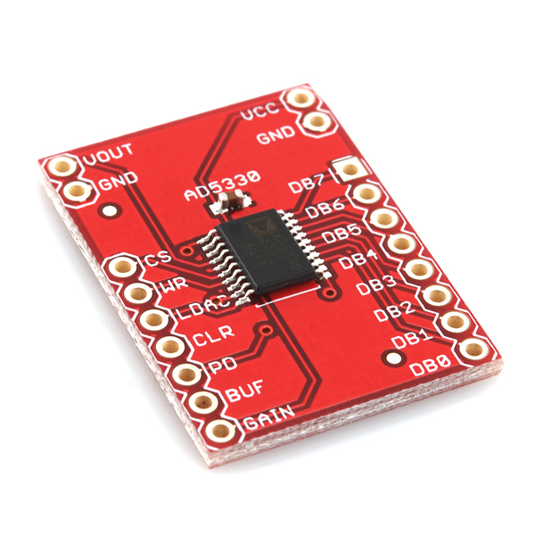
This is a simple breakout board for Analog Device's AD5330 8-bit digital-to-analog converter (DAC). The AD5330 has a parallel interface, and can operate from a 2.5 to 5.5V supply consuming just 115uA (at 3V).
The DB0-7 pins, the parallel data inputs, are used to configure the analog output voltage. CS selects the device, and data is loaded into the input registers on the rising edge of WR. The GAIN pin allows the output range to be set at either 0V to VCC or 0V to 2VCC.
Input data to the AD5330 is double-buffered, allowing simultaneous update of multiple DACs in a system using the LDAC pin. An asynchronous CLR input resets the contents of the input register and the DAC register to all zeros. The AD5330 also incorporates a power-on reset circuit that ensures that the DAC output powers on to 0V and remains there until valid data is written to the device.
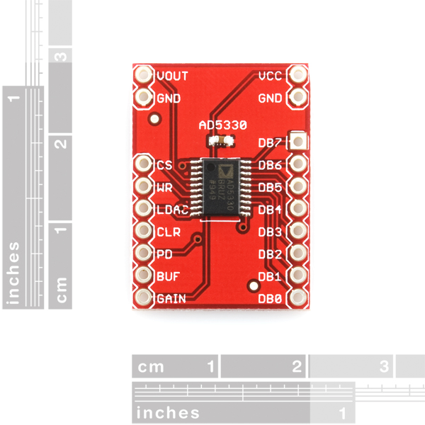
This breadboard friendly board breaks out every necessary pin of the AD5330 to 0.1" spaced headers. The board includes a decoupling capacitor, but does not do any voltage regulation; voltage supplied to the board should be within the specified range.
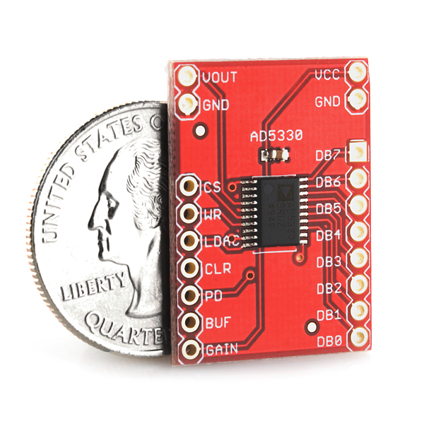
- 0.80 x 1.10"
Breakout Board for AD5330 Parallel 8-Bit DAC Product Help and Resources
Core Skill: Soldering
This skill defines how difficult the soldering is on a particular product. It might be a couple simple solder joints, or require special reflow tools.
Skill Level: Noob - Some basic soldering is required, but it is limited to a just a few pins, basic through-hole soldering, and couple (if any) polarized components. A basic soldering iron is all you should need.
See all skill levels
Core Skill: Electrical Prototyping
If it requires power, you need to know how much, what all the pins do, and how to hook it up. You may need to reference datasheets, schematics, and know the ins and outs of electronics.
Skill Level: Rookie - You may be required to know a bit more about the component, such as orientation, or how to hook it up, in addition to power requirements. You will need to understand polarized components.
See all skill levels
Comments
Looking for answers to technical questions?
We welcome your comments and suggestions below. However, if you are looking for solutions to technical questions please see our Technical Assistance page.
Customer Reviews
No reviews yet.
Any chance of seeing a serial input DAC, like the AD5337?
See below. I2C DAC.