
ProtoScrewShield Kit Retail
The ProtoScrewShield, a portmanteau (I had to look it up) of words that conjure up images of frustratingly drilling a prototype into an Arduino (who hasn't been there?). That's not quite what we're going for, but if you're imagining a versatile prototyping shield, that can interface with just about any electronic component, you're definitely on the right track. The ProtoScrewShield combines our proven Arduino ProtoShield with always-useful screw terminals.
In this guide we'll effort to get you a fully assembled, hopefully functional, ProtoScrewShield. The assembly section will be followed by some usage hints, just a little something to push you in the direction of your next project.
Assembling the ProtoScrewShield
You've probably noticed that the product you received looks nothing like the pretty picture on the packaging. Before you can start prototyping, screwing, and...err...shielding, you need to assemble the ProtoScrewShield. Assembly is pretty straightforward, but it will require simple, through-hole soldering. If this is your first time picking up a soldering iron, I'd encourage you to first foray into one of our excellent soldering tutorials. We don't want anyone's ScrewShield to end up looking more like a piece of modern art, than a usable Arduino shield (yeah, that sentence exists solely for the purpose of linking a Simpsons clip).

At a minimum, the required tools for assembly are a couple opposable digits, a really basic soldering iron, a bit of solder, and some cutters. In addition to those tools, other items you might find helpful include needle nose pliers, and perhaps a third hand, or vise, to keep everything nice and stable.
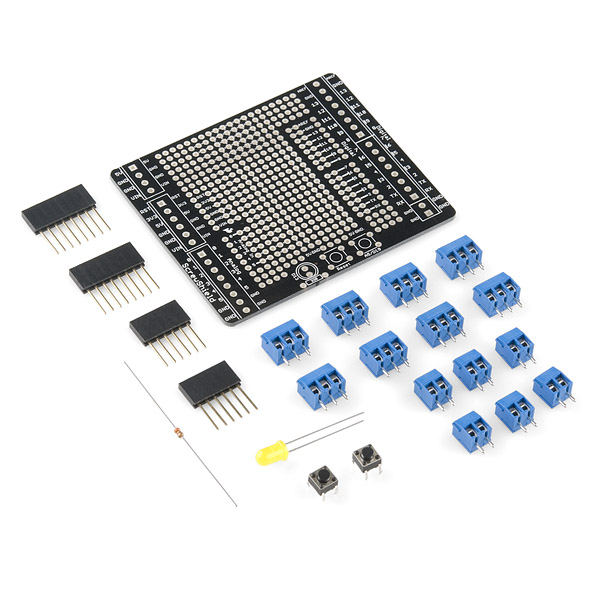
Before beginning assembly, empty out your bag and make sure you've got all the parts you should:
- 1x ScrewShield PCB
- 1x 5mm Yellow LED
- 1x 330Ω Resistor
- 2x 6-pin Stackable Headers
- 2x 8-pin Stackable Headers
- 2x Momentary Push Buttons
- 6x 2-pin 3.5mm Screw Terminals
- 8x 3-pin 3.5mm Screw Terminals
Missing any parts? (Bad SparkFun kitters!) Drop our customer service team an email. We'll get them out to you as soon as possible.
Now, dig out the ScrewShield PCB and get yourself acquainted with it. If you're like me, you'll probably have to flip it over and back a couple dozen times to figure out which side is the top. To avoid assembling the shield upside-down, remember that the top of the PCB is the side with the outlines of all the parts. It looks like this:

You'll be inserting every component on the top side of the PCB, and soldering the leads to the bottom side.

MSPAINT skills beyond compare...
If it wasn't already obvious enough, the diagram above should be a good guide as to where each component should ultimately find itself on the ProtoScrewShield. I'd recommend working from the lowest-profile component up, meaning start with the 330Ω resistor, followed by the buttons, LED (be careful of the polarity!), and finally the stackable headers. This method usually ensures that the components are seated as flush with the PCB as possible. You want your ProtoScrewShield to look pretty enough to take home to Ma, don't you?
One special note on the headers, well two actually. The labels on the board aren't nearly as clear as they should be; make sure you insert the headers exactly where they're slated to go in the diagram above. There's a few places the headers look like they could be inserted, and if they don't go into the outermost of those locations, your shield will not be Arduino-compatible. Secondly, when soldering you headers, take care to keep them as straight as possible. I like to solder the first pin of each header, and then plug it into my Arduino to make sure everything lines up, before soldering all six, or eight, pins of the header.
Now, all that remains are the screw terminals. If you haven't noticed how much these screw terminals rule, I invite you to take a closer look. Have you noticed how they slide together to form mega-screw-terminals? Use the combinations of 2- and 3-pin screw terminals to form mega-screw-terminals of 2, 4, 6, and 8 (three of these) varieties. You should have enough screw terminals to complete all of the necessary mega-screw-terminals, and fill out your ProtoScrewShield. Take care to ensure that the screw terminals slide into each other evenly.
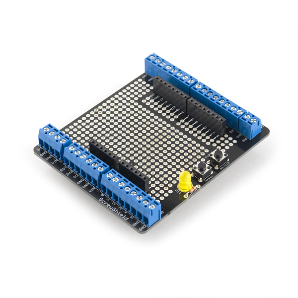
With you mega-screw-terminals all complete, insert them into their corresponding footprints on the PCB. Verify that all inputs of the screw terminals are facing towards the outside of the PCB. Hold each screw terminal in place as you flip the board over and solder them into place. These larger pins may require an extra bit of solder. If your ProtoScrewShield looks something like the picture below, congratulations! If not, well, maybe you should invest in some solder wick; it's never a bad time to learn how to desolder!
How to use the ProtoScrewShield
The prototyping area of the ProtoScrewShield looks easy enough to use, but it can be hazardous to your circuit's health if you take to soldering parts to it without any planning. Unbeknownst to many the prototyping section of the ScrewShield is actually much more complex than it looks. It's full of 5V and GND rails, grids and triads of interconnected pins, and extensions of the Arduino headers.

I bet you didn't expect there was that much going on behind the scenes. Power and ground rails can be among the most useful components on a prototyping board. What's great about the power rails on the ScrewShield is there's two pairs, and they're separated by exactly four rows of unconnected prototyping holes. What's great about four rows of unconnected prototyping holes, surrounded by power rails? Well, most through hole chips that come in a 32-pin or less DIP package are 0.3" wide; that means DIP chips will sit perfectly between their neighboring power rails. You could stick an ATmega328 in there and wire yourself up a second Arduino, op-amps, 555 timers, shift-registers, motor drivers, the list of compatible chips just goes on and on. This is a major bonus, because wiring stuff by hand sucks, and keeping power lines as short as possible is awesome!
Also adjacent to the power rails are the what I call the floating triads of pink pins, err at least they're pink in my diagram. These could have any number of uses, but the one that sticks out to me is their inherent compatibility with servos. The standard pinout for a servo is negative power, positive power, signal, which matches up well with the left power rail and the pink triads. You could solder a trio of male headers into a power rail and single pin of the triad, solder a second pin of the triad to a PWM Arduino pin, and you've quickly got an output for a servo.
The gridlocked proto pins may look somewhat unusable, unless you have hobby knife. Cutting PCB traces is a tradition that goes back through generations of engineers who've all had a moment of PCB-design-weakness and thrown in a spurious wire trace. A gridlocked prototyping area can really cut down on wiring, but you'll probably need to attack the traces on the back of the board with a blade, to make sure nothing is shorted that shouldn't be.
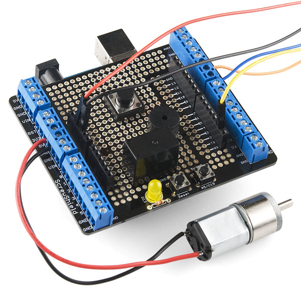
And let's not forget the shared namesake of the ProtoScrewShield, the screw terminals. A lot of electronics components don't care that they're not Arduino-compatible (how inconsiderate). For instance, any good electronics hobbyist has a special place in their heart for stranded wire, but the damn stuff just never wants to be inserted into a female header without fraying all over the place. If you don't want to deal with the permanence of soldering that wire, screw terminals are a great option that still leaves you with a solid, physical connection. Screw terminals can be a great way to interface with motors, sensors, or LEDs, just don't forget the screwdriver!
Making use of the ProtoScrewShield
With the ProtoScrewShield fully assembled, and the intricacies of it use clear, the onus is on you to do something amazing with it. Make us proud! If you'd like to tell us how you used your ScrewShield, drop us a line!
Have a suggestion for how we can improve this guide? Steps missed? Instructions unclear? Please let us know. You can leave a comment below or email us spark@sparkfun.com. Also let us know if this is the most awesome assembly guide you've ever encountered and we'll stop trying to improve it.
What does the A5/D19 button do?
Momentarily connects A5 to ground.