- Home
- Product Categories
- Current
- SparkFun Coulomb Counter Breakout - LTC4150

SparkFun Coulomb Counter Breakout - LTC4150
Odometers are extremely useful for cars, they tell you how far you have gone, wouldn't it be nice if you were able to have a device that does the same for electrical current? The LTC4150 SparkFun Coulomb Counter Breakout is here to be your odometer for current. If you are wondering: a coulomb is defined as, to put it simply, one amp for one second. This breakout is capable of constantly monitoring the current your sensor is using, is able to add it up, and will give you a pulse each time a given amount of amp-hours have been used. When used effectively and if you start with a full battery, you’ll always know exactly how much of it is left!
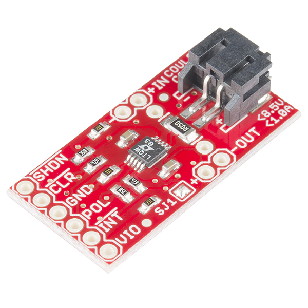
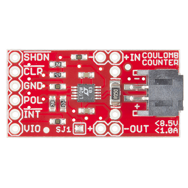
At one end of the Coulomb Counter Breakout are headers labeled IN and OUT. Connect your battery or power supply to the IN header or JST battery connector (they’re identical), and connect the OUT header to your project. At the other end of the Coulomb Counter you’ll find a header with six pins. These are the pins you’ll need to connect to your microcontroller and include VIO (Voltage Input), INT (Interrupt), POL (Polarity), GND (Ground), CLR (Clear), and SHDN (Shutdown). Simply install this breakout out between your power source and your circuit, that way all the current your circuit uses needs to pass through the Coulomb Counter to be measured.
- Operating Voltage: 2.7V - 8.5V
- Operating Current: 1A
- Indicates Charge Quantity and Polarity
- ±50mV Sense Voltage Range
- 32.55Hz/V Charge Count Frequency
- 1.5μA Shutdown Current
- Schematic
- Eagle Files
- Hookup Guide
- Datasheet (LTC4150)
- GitHub (Example Code & Design Files)
- Product Video
SparkFun Coulomb Counter Breakout - LTC4150 Product Help and Resources
LTC4150 Coulomb Counter Hookup Guide
September 18, 2014
A "Coulomb Counter" is like a gas gauge for your battery. Here's how to use it.
Core Skill: Soldering
This skill defines how difficult the soldering is on a particular product. It might be a couple simple solder joints, or require special reflow tools.
Skill Level: Noob - Some basic soldering is required, but it is limited to a just a few pins, basic through-hole soldering, and couple (if any) polarized components. A basic soldering iron is all you should need.
See all skill levels
Core Skill: Programming
If a board needs code or communicates somehow, you're going to need to know how to program or interface with it. The programming skill is all about communication and code.
Skill Level: Rookie - You will need a better fundamental understand of what code is, and how it works. You will be using beginner-level software and development tools like Arduino. You will be dealing directly with code, but numerous examples and libraries are available. Sensors or shields will communicate with serial or TTL.
See all skill levels
Core Skill: Electrical Prototyping
If it requires power, you need to know how much, what all the pins do, and how to hook it up. You may need to reference datasheets, schematics, and know the ins and outs of electronics.
Skill Level: Competent - You will be required to reference a datasheet or schematic to know how to use a component. Your knowledge of a datasheet will only require basic features like power requirements, pinouts, or communications type. Also, you may need a power supply that?s greater than 12V or more than 1A worth of current.
See all skill levels
Comments
Looking for answers to technical questions?
We welcome your comments and suggestions below. However, if you are looking for solutions to technical questions please see our Technical Assistance page.
Customer Reviews
4.2 out of 5
Based on 6 ratings:
1 of 1 found this helpful:
Good for the exact purpose specified, but ...
This seems like a terrific breakout to track charge/discharge on a battery. It accumulates a net change in charge and interrupts the host microcontroller
I had a little bit different application in mind, which was to track current draw of an Arduino differentiating states of high draw and low draw (as, for example, when the processor is sleeping). Unfortunately, when you do the math, the Coulomb counter will interrupt its host microcontroller at most once every 0.6 seconds and it will be only that frequent if the CC is measuring the maximum current draw for the sense resistor in place. If the current draw is less it could be many seconds between interrupts.
It would be great if it were possible to reduce the downscaling on the board from 1024 to 128 or even 1. That would enable a finer resolution on the time at various current levels.
2 of 2 found this helpful:
Handy little board
I wanted to use this board to monitor the performance of an energy harvester, so I needed more than the default sensitivity. Accordingly, I unsoldered the 50mΩ resistor provided and used the provided through holes to install a 51Ω resistor, increasing the sensitivity by lightly over a thousand. Now, with a 5µA current, I get an interrupt every couple of minutes, and a simple Arduino sketch can convert that to current. However, this use case doesn't fit the "I'm being powered by the battery" assumption built in to the board, which made things a little tricky. Perhaps another jumper to disconnect the Vdd pin from the Vout+ pin? Additionally, one to connect Vdd to Vio would have been perfect for my application.
0 of 1 found this helpful:
Works well
Very easy to use. Had no trouble getting it up and running quickly. Looking forward to playing around with it further.
Great for basic battery life prediction
This product does a great job with measuring moderate to high currents from 1mA, to 50-100mA or even more. If you're trying to track extremely low current accumulations (majority of time spent in uA range), you might consider swapping out the sensing resistor for a higher value, but of course this would yield a higher voltage drop across the device for 'run' current. If you use the self-clearing feature of the /INT line, be aware that this pulse width can be extremely short, on the order of a couple of uSecs, so either use a h/w IRQ line or a counter input, or switch over to manually resetting it via the /CLR line (you have to leave /INT asserted for at least 20uS before you clear it). NIce product for gathering real-world data!
Looks promising
This looks like it would do the job I want. While the assumption that the counter chip is powered by Vin does not hold up well in practice, never underestimate the power of an X-Acto knife, a fine-tip soldering iron, and 30ga silicone wire to fix this problem. A 3-pin header with a jumper would have been better, allowing me to choose VIO or VIN. I plan to have several boards, with different values of resistors, and a relay external to the board to switch between VIN of the board and an internal-to-my-project Vref, and the ability of the software to select the voltage source going to the VIN of the chip. The idea is that during startup() the program will select Vref, and after a few seconds it will know which board was used. The design uses DuPont connectors on the board; to swap boards, disconnect the pins (three connectors), and replace it with a different board with a different Rsense, plug all the cables in, and the software will calibrate itself.
A serious defect is that there is no fritzing file for this part. This and the need for an X-Acto knife is why I am giving it only a 4.
Vsense = ,050, max 1A Vsense = .100, max 500ma Vsense = .200, max 250ma Vsense = .500, max 100ma Vsense = 1.0, max 50ma Vsense = 5.0, max 10ma
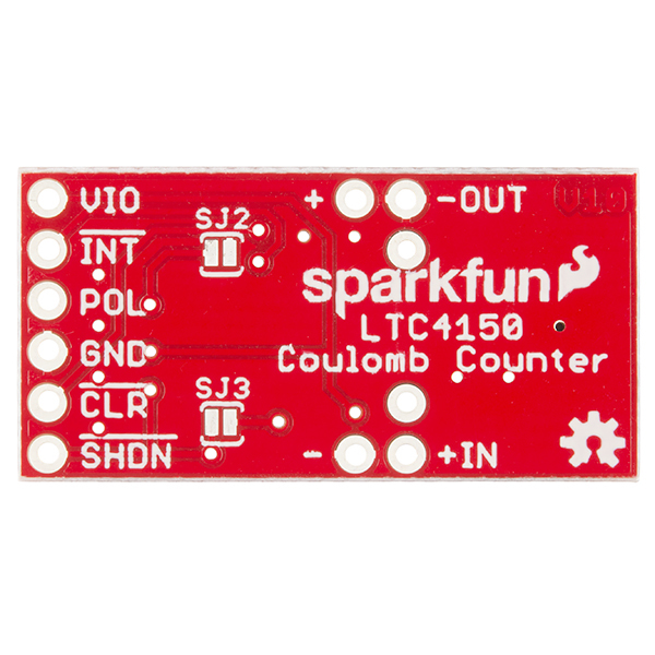
I was using this device with a Raspberry Pi Zero W and it works great. Creating an interrupt in my python code made the 2 devices talk without any problems. It does require closing the jumpers on the back side of the board but did not require changing any of the values. This will become a staple tool in the workshop
To exclude the sensor's energy consumption from the total count...
TL;DR: If you don't want the energy consumed by the LTC4150 and pull-ups included in the total count, simply swap input and output.
Details:
Like others, I have an application where I don't want the energy consumed by the LTC4150 counted towards the total.
To the best of my understanding, you can solve that by simply by connecting your power source to the output terminals and your load to the input terminals. This works because the device measures bi-directional current, and takes its power from the "output" side of the sense resistor.
I infer this from reading the data sheet and the schematics, but someone should back me up on this!
I would like to use this to monitor power bidirectionally between battery and charging circuit. Is it safe to put the charger at the OUT header and the battery at the IN header?
The LTC4150 data sheet says it should be:
I tried it, works fine. The charger sends in coloumbs at about 760 mA! Thanks for a great little board, Sparkfun.
Off the top of my head, because the board is bidirectional, that should work fine. The polarity indicator will just be reversed from "normal".
BE CAREFUL IF YOU ARE POWER CONSTRAINT.
Using it with a solar project. It works but the breakout is REALLY BAD DESIGN, imho. The problem is that the board leaks ~1mA through idiotic pull-ups (POL and others). It should not be surprising that this is used in context with very limited power supply. which makes the sloppy design even more embarrassing for Sparkfun. Please please update this!
So my current design uses 1,12mA when in power saving. 1mA for the coulomb counter and 120uA for everything else. rolleyes
Hi - if you don't want the power consumed by the breakout board to be counted in the total, simply swap the input and output (see other comments above for why this works).
Separate from that, it sounds as if 1A full scale is too large for your needs -- you can replace the 0.05 ohm shunt resistor with a larger value (0.5 ohms for 100mA full scale, 5 ohms for 10mA, etc).
Between those two tweaks, this board might work better for you.
Another good application: electric wheelchair batteries. 24V, OMG amps (but well under fifty), very flat discharge until the critical point when voltage drops abruptly. Having an "estimated hours of battery remaining" or some other representation other than the trivial voltmeter they come with would be a great device. I can start out with what appears to be a full charge and a block later I'm looking for someone to give me a push! A few experiments counting coulombs before battery discharge, and I've got a "countdown timer" for actual usage.
Don't count your coulombs before they're hatched...
I agree with the comments so far - with a much higher rating of current, this would be very handy for a number of things. Monitoring status of your RV or boat batteries would be big. I just made one for my boat using a shunt resistor. A Hall Effect transistor may be a better way. Check it out Sparkfun!
For an RV or boat, check out this: http://www.bogartengineering.com/products/TriMetric. Substantially more expensive, but specifically designed for the higher currents (a few hundred amps.) And if your rig has a Magnum Energy inverter and remote, this one plugs right in and will even start the generator when the batteries drain to a set state of charge: http://magnumenergy.com/battery-monitor-kit-me-bmk/
This coulomb counter is for MUCH smaller battery systems, obviously designed for small portable electronics. It should give a much more accurate approximation of the battery state, compared to just measuring voltage, especially for batteries that have a rather flat discharge curve.