- Home
- Product Categories
- Arduino Boards
- Qduino Mini - Arduino Dev Board

Qduino Mini - Arduino Dev Board
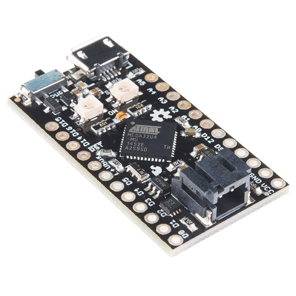
The Qduino Mini is a tiny, Arduino-compatible board with a battery connector and charger built-in as well as a fuel gauge that can tell you when to charge the battery! This little guy is super small, inexpensive, and is perfect to embed in your electronics projects. The Qduino Mini is the same model awarded to its Kickstarter backers and is Arduino-compatible and 100% open source, meaning that making and programming your first circuit is a breeze.
Here's what the Qduino includes:
- Battery Charger Circuit - just plug in a USB the battery starts charging with the auto switching circuit - there's no extra charger needed and no digging the battery out of your project so you can charge and program at the same time over USB!
- Battery Fuel Gauge - guessing on when your project runs out of juice? We've got you covered - we have a simple monitor library for your battery so you can remind yourself when it needs that little extra power.
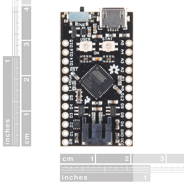
- Ultra small, Ultra thin, Ultra light - The Qduino Mini itself is 0.8in x 1.5in (2cm x 3.8cm) and 0.125oz (3.5 grams), perfect for quadcopters, drones or high altitude balloon projects.
Additionally, each Qduino is also breadboard compatible and has two RGB LEDs. One for status and another that is user programmable!
Note: Please be sure to double check your board type before uploading to make sure you have “Qduino Mini” selected in the IDE. Otherwise, you could potentially brick your new Qduino board.
Note: A portion of each sale is given back to Quin Etnyre of Qtechknow for continued development into the world of electonics.
- ATmega32U4 Processor
- 32KB Flash Storage
- 2.5KB SRAM
- 1KB EEPROM
- 3.3V @ 8MHz
- 19 Digital I/O // 13 Dedicated
- 12 Analog Channels // 6 Dedicated
- 7 Digital I/O also PWM channels
- SPI, I2C, UART available
- Two RGB LEDs built-in - one for: Charge Status, TX, RX, and the other user programmable
- AP2112K 3.3V 600mA Regulator
- MCP73831 LiPo Battery Charger
- MAX17048 LiPo Battery Fuel Gauge
Qduino Mini - Arduino Dev Board Product Help and Resources
DIY Light-Up Shoes
September 28, 2017
This tutorial provides everything you need to know to make your own light up high top sneakers!
DIY Light Sculpture
August 23, 2018
In this digital fabrication project featuring 3D printing, laser cutting, and DIY electronics, you will build a beautiful design object for your desktop or night stand.
Choosing an Arduino for Your Project
December 11, 2017
Examining the diverse world of Arduino boards and understanding the differences between them before choosing one for a project.
LiPo Fuel Gauge (MAX1704X) Hookup Guide
February 23, 2023
Monitor your LiPo battery with the LiPo fuel gauge! In this tutorial, we will be using the MAX17043 and MAX17048 to monitor a single cell, LiPo battery over the Arduino Serial Monitor. We will also connect a display to view the output without the need to connect the microcontroller to a computer.
Pro Micro & Fio V3 Hookup Guide
November 8, 2013
An overview of the Atmega32U4-based Pro Micro and FioV3, how to install it, and how to use it with Arduino.
Bricked Atmega32U4
-------------------- Tech Support Tips/Troubleshooting/Common Issues --------------------
Bricked Atmega32U4
Timing Issues w/ USB Communication through CDC
Interrupts Atmega32u4's built in CDC driver for USB communication can have timing issues when messing with the watchdog timer, sleep modes, and timer interrupts. I am unsure of how to fix this issue if you continue to use code that interferes with the CDC. I recommend trying a different method than using the interrupt timers.
Wrong Bootloader It's possible to brick your QDuino if you used the wrong board selection with the wrong frequency. If you upload the wrong frequency, the IC will not be able to understand any new code that is being uploaded. It expects to have code that is compiled for another bootloader, instead of using the 8MHz frequency with the oscillator.
When either of these cases happens, the device manager is not able to recognize the device and is usually seen as an "unknown device" when the microcontroller runs the sketch. There are ways to recover the an Atmega32U4 (i.e. LilyPad Arduino USB - Atmega32U4 board, FioV3 - Atmega32U4, Pro Micro 5V/16Mhz, Pro Micro - 3.3V/8Mhz, etc) if this happens. Check below for more information:
A.) Upload when QDuino/LilyPad USB with Atmega32U4/Pro Micro/FioV3 is still in Bootloader Mode
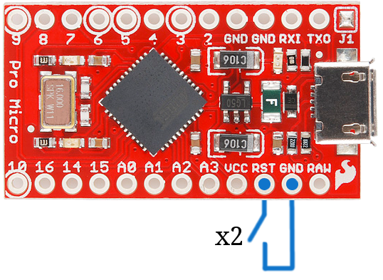
You can try the double reset method by tapping the RST pin to GND twice (since there is no reset button on the board) as explained in the Troubleshooting sections labeled as Reset to Bootloader and How to Revive a "Bricked" Pro Micro => https://learn.sparkfun.com/tutorials/pro-micro--fio-v3-hookup-guide/troubleshooting-and-faq.
1.) Open the Arduino IDE.
2.) Choose a simple code to upload on the Arduino. I used the blink test code from the hookup guide [ https://learn.sparkfun.com/tutorials/pro-micro--fio-v3-hookup-guide#example-1-blinkies ] to upload.
3.) Check your Tools>Port menu for the list of COM ports when the Arduino is connected. You will probably not see it in the list.
4.) Click somewhere else to stop viewing the list of COM ports.
5.) Ground the RST button 2x as stated in the Troubleshooting and FAQ [ https://cdn.sparkfun.com/assets/6/d/3/4/a/523c8e23757b7fbe5f8b4584.png ].
6.) Re-open the Tools>Port menu to view the list of COM ports again to see what the QDuino enumerates to when its in its bootloader. There is an 8 second window to view the COM port when the board is in bootloader mode.
Note: Feel free to use the device manager at this step. Opening up the device manager on your operating system will help to see when the Arduino pops up and disappears.
7.) Select the COM port that the QDuino is on before it disappears again.
8.) Hit the Upload button to compile and upload.
9.) Wait a few seconds for the Arduino IDE to compile code. The progress bar should be just over the halfway mark.
Note: On Windows, this takes about 20 seconds to compile and upload. The device will show up as "Qduino Mini bootloader (COM##)". Trying this on a Mac seemed a little faster to compile and upload.
10.) Hit the reset button twice again to place the QDuino in bootloader mode while the Arduino IDE is uploading.
11.) If successful, you will have no error messages the Arduino IDE will tell you that it is "Done uploading."
After selecting the correct board definition and timing the double reset method correctly, I was able to upload successfully. It took me a couple of tries before I could get this right because of the timing. You should not need to go through this recovery procedure for subsequent uploads unless you brick the Atmega32U4 again.
---------------------------------------------------------------------------------------------------
B.) Outdated or Corrupt drivers
If board is showing up as Qduino Mini bootloader (COM##) or Arduino Micro (COM##) or Pro Micro (COM##), try the double reset method and updating the drivers while still in bootloader mode:
1.) Use the double reset method while having the device manager open.
2.) When the board entered the bootloader mode, I right-clicked on the Arduino board in the device manager as shown in this screen shot: [ http://puu.sh/iaYYC/d45153914c.png ]
3.) I updated the driver for the board.
4.) Once the update was completed, I compiled and uploaded the code. When the uploading status bar was half-way through, I did double reset again and the problem was fixed.
---------------------------------------------------------------------------------------------------
C.) Reinstalling the Bootloader
As a last result, you can always try to reinstall the bootloader. The tutorial is designed for the Arduino Uno, but it should work for Atmega32U4's bootloaded with Arduino. The idea is the same but the specifics are different. Start by reading the tutorial => https://learn.sparkfun.com/tutorials/installing-an-arduino-bootloader. The first thing you are going to need is an AVR programmer. You can use a standard AVR programmer or any Arduino with the ISP code on it (the standard code will not work with the Leonardo). You will then need to connect it to the target device (i.e. QDuino, LilyPad Arduino USB, Pro Micro, Fio V3, Makey Makey, or Leonardo) to reflash the bootloader. Don’t worry about the fuse bits or even the avrdude commands (they’re great, if you are installing third party stuff, but this will work just fine).
1.): Get a programmer
This you can do by following the directions in the tutorial.
2): Connect the programmer/Arduino as ISP to the Target Device
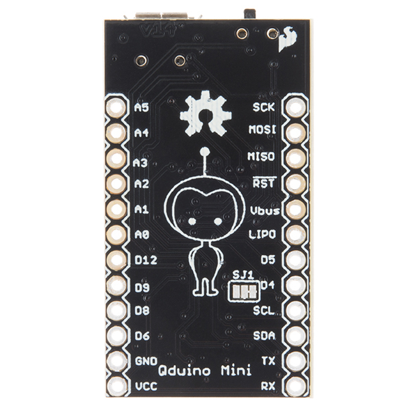
You will need to connect to the same pins to your target device (i.e. QDuino, LilyPad Arduino - USB, Pro Micro, Fio V3, Makey Makey, or Leonardo). On the Leonardo you can connect it just like the Uno. The LilyPad Arduino - USB has small ICSP pins. I managed to solder wires directly to the pins for access. The QDuino and Pro Micro does not have an ISP header and the pin numbers are different. Check the tutorial for location of the pins on the programmer. Here are the pins for the QDuino:
ICSP Pins <=> QDuino
   GND    <=>      GND
   RST    <=>      RST
   VCC    <=>      VCC
   MISO   <=>      D14
   SCK    <=>      D15
   MOSI   <=>      D16
Note: There is a silkscreen error and D17 is labeled D14 on the Pro Micro.
3.) Program Using Arduino v1.6+ go under Tools and select the correct programmer (if your programmer uses a COM port select that too), and the correct board (QDuino, LilyPad Arduino - USB, Pro Micro, FioV3, Makey Makey, or Leonardo). Then select Burn Bootloader. For the QDuino, this will use the bootloader in the addon file, so make sure you have the correct addon file installed. You can find the latest board definitions from the SparkFun GitHub Repository [ https://github.com/sparkfun/Arduino_Boards ].
QDuino-specific driver
If you are looking for a Qduino-specific driver, it can be found here:
https://github.com/MightyQ/Qduino_Mini
It is the /Software/qduinomini.tar file.
Core Skill: Soldering
This skill defines how difficult the soldering is on a particular product. It might be a couple simple solder joints, or require special reflow tools.
Skill Level: Noob - Some basic soldering is required, but it is limited to a just a few pins, basic through-hole soldering, and couple (if any) polarized components. A basic soldering iron is all you should need.
See all skill levels
Core Skill: Programming
If a board needs code or communicates somehow, you're going to need to know how to program or interface with it. The programming skill is all about communication and code.
Skill Level: Rookie - You will need a better fundamental understand of what code is, and how it works. You will be using beginner-level software and development tools like Arduino. You will be dealing directly with code, but numerous examples and libraries are available. Sensors or shields will communicate with serial or TTL.
See all skill levels
Core Skill: Electrical Prototyping
If it requires power, you need to know how much, what all the pins do, and how to hook it up. You may need to reference datasheets, schematics, and know the ins and outs of electronics.
Skill Level: Rookie - You may be required to know a bit more about the component, such as orientation, or how to hook it up, in addition to power requirements. You will need to understand polarized components.
See all skill levels
Comments
Looking for answers to technical questions?
We welcome your comments and suggestions below. However, if you are looking for solutions to technical questions please see our Technical Assistance page.
Customer Reviews
4.6 out of 5
Based on 5 ratings:
1 of 1 found this helpful:
An Arduino whose time has come
I wish I had this when I built my last battery powered Arduino project. The onboard battery charger/regulators are something that should be included with every Arduino (in my humble estimation). The battery level indicator is also critical - on my last project I had no way to show the batt level. Kudos. The only thing I would like to see, eventually, is a larger/faster Atmel processor. I made a quick video about this on my YouTube channel.
https://www.youtube.com/watch?v=i0mx0lrGHIw
1 of 1 found this helpful:
"almost" perfect
I have one and am trying to base a project around it, because the integrated battery charger is great -- I can plug it in to charge a battery without worrying about swapping batteries.
However, the problem I'm running into relate to the pins they chose to use for the user controlled LED -- I want to do audio using something like Mozzi, which can do high quality audio using PCM output on two pins on the same timer. By default, Mozzi uses 9 and 10, but 10, 11 and 12 are used by the LED. Most of the pairs of the timer pins that could be used for this seem to need one of these pins. Frustrating.
I'd be happy to do away with the LED to have more flexibility in how I use those pins!
1 of 2 found this helpful:
Awesome Product!
One review is worried that this board is missing pins 10, 11, 13. They're actually available (and disguised) on the board as the "MISO MOSI & SCK / D14, 15, 16" pins. These ARE pins 10, 11, 13 according to the designer. So this board is a complete Arduino board with the added bonus of an extra LED for status reports.
Slightly confusing setup process but incredibly useful Arduino board
One of the first hurdles was setting up the board in the Arduino environment.
For Step 2 of the Quick Start guide, it says to scroll down to "Qtechknow Boards" in the Boards Manager. If you can't find that, try "Qduino" instead.
For Step 2.5 (for the Windows driver installation), the folder that is being referenced is typically under C:\Users(username)\AppData\Local\Arduino15\packages\SparkFun\hardware\avr\1.1.7\signed_driver
The rest is pretty straightforward.
As for the actual Arduino, it works like a dream! I used this for my battery-powered Halloween costume that used 24 RGB LEDs and a 1.5Ah battery, and it lasted the entire day. I switched the charging current from 100mA to 500mA using the solder jumper and the charging time was pretty quick.
My only gripe is that you can't see the charging status when the power switch is off, so it may not be clear that the battery is charging. After looking over the schematic though, it becomes apparent that it is in fact charging and being all kinds of awesome.
Overall, it's a great Arduino dev board for Li battery-powered projects, and certainly a welcome addition to the Arduino hardware world!
Hi. Have any of you used this with a LiPo and solar panel? Can it manage charging of the battery when possible and switching to just battery when solar power supply is low?
We haven't tested a LiPo and solar panel, but theoretically it should work. The solar panel should be hooked up to the USB pin (5V preferably, I would have to double check for higher voltage), and then it would charge the battery when there was sunlight. If there is no sunlight / solar supply is low, it will run off of the battery instead without having to manually switch the connections. The Qduino's 'preferred' place where it gets power is the USB connector / USB pin, and its 'backup' is the LiPo battery, in other words, it will always automatically switch to the higher voltage (it will always run off of the 5V USB connection instead of the 3.7-4.2 volts LiPo battery connection).
I haven't tried this, but did some quick research. If you want to protect your battery you would ideally run this power through the LiPo charger. This is trace broken out and labeled VBUS. This is as Quin explained. The issue here is that the VBUS pin on the ATmega has an absolute maximum rating of +6.0V. Keep this in mind. Also consider using a Schottky diode to prevent running power into the solar panel.
(when the USB connection / solar panel is connected)
Are you sure the "SparkFun Pro nRF52840 Mini - Bluetooth Development Board" (DEV-15025) is an essential product?
Well, that shouldn't be there. It has been removed!
I've experienced what I expect to be a software bug. I was working on a UART data capture device, logging the data to a SD card which simultaneously passes the data through the USB based com port. The single cell battery circuitry provided a convenient backup to ensure all the data was captured if the USB cable was inadvertently disconnected. When initializing an SD card via the SPI port (CLK D15, MOSI D16, MISO D14, SS D5) the COM port through the micro USB no longer functions. Using the hardware UART module I was able to work around the issue. Being opensource, I guess I can look for a solution.
Quick question, according to the schematic the Vcc pin can provide 600 ma at 3.7 volts. Is this a correct interpretation of the documentation? Would drawing 400 ma - 600 ma from the Vcc port damage this board?
Does the Qduino cut itself off under a certain voltage (of the battery) in order to prevent the Lipo to be over discharged (and damaged) ?
Hi. I've got a project set up with a Qduino that's trying to use Mozzi for audio. It's working with Arduino 1.6.4, but the sound is awful. After struggling with things for a while, I realize that (for some reason) Mozzi doesn't work well with the recent Arduino IDE's. Can someone give me some pointers on how to set up 1.0.5 to work with the Qduino.
I've grabbed the installer files, and have tried moving them into the appropriate places inside Arduino 1.0.5. I see qduino on the boards list, I can compile: but it's not uploading. I suspect this has to do with me not knowing what to do with the avrdude.conf and platform.txt files that are there.
If anyone knows how to get this working on 1.0.5, I'd appreciate some pointers!
I'd take a look at boards.txt. It has changed since that older version. Here is a place to start. I didn't use Arduino back the the pre-1.5.x days, so I don't really know how it worked. The documentation must still be around. You might also use the boards.txt from the Leonardo in version 1.0.5 and change the clock speed to 8MHz and the VID/PID. BE VERY CAREFUL. If you use the wrong clock speed of if there is another important setting that I'm overlooking it might be a pain to get the Qduino Mini running again.
Couldn't get it working, alas. In the end, I just desoldered it, tossed it in the drawer and switched to one of the Pro Mini's (5V/16Mhz) I had sitting around. Had to switch to AA batteries (sadness) for now (and rework and re-print the case to hold them), but it worked straight-away. 8Mz was probably too slow for Mozzi anyway.
The Arduino really just needs an entry in the boards.txt file for the Qduino (at least in the 1.0.x version of the IDE). This uses the same IC as the Leonardo and the Pro Micro. I'd grab the configurations settings from one of those and add an entry for the Qduino. Make sure the speed is correct and you will probably want to update the VID/PID. If you are still having problems feel free to email techsupport@sparkfun.com and they should be able to help you out.
Hey there. I just got my qduino - and I followed (best as possible) the instructions on the quick start. All seems well but when I try to upload I get:
ava.io.IOException: Cannot run program "REMOVE/bin/avrdude": error=2, No such file or directory at java.lang.ProcessBuilder.start(ProcessBuilder.java:1048) at java.lang.Runtime.exec(Runtime.java:620) at java.lang.Runtime.exec(Runtime.java:485) at processing.app.helpers.ProcessUtils.exec(ProcessUtils.java:11) at cc.arduino.packages.Uploader.executeUploadCommand(Uploader.java:113) at cc.arduino.packages.uploaders.SerialUploader.uploadUsingPreferences(SerialUploader.java:157) at cc.arduino.UploaderUtils.upload(UploaderUtils.java:78) at processing.app.Sketch.upload(Sketch.java:1178) at processing.app.Sketch.exportApplet(Sketch.java:1152) at processing.app.Sketch.exportApplet(Sketch.java:1124) at processing.app.Editor$DefaultExportHandler.run(Editor.java:2452) at java.lang.Thread.run(Thread.java:745) Caused by: java.io.IOException: error=2, No such file or directory at java.lang.UNIXProcess.forkAndExec(Native Method) at java.lang.UNIXProcess.<init>(UNIXProcess.java:248) at java.lang.ProcessImpl.start(ProcessImpl.java:134) at java.lang.ProcessBuilder.start(ProcessBuilder.java:1029) ... 11 more
Anyone see something similar?
Thx.
Which version of the Arduino IDE are you running? They broke the board manager starting in version 1.6.6 through the last hourly build I've tried. Uninstalling, and reinstalling the board support files along with some IDE restarts can clear this up, but I prefer to run 1.6.5-r5 because it just works. Make sure you have the latest board support files from our Arduino Boards repository. Here is the URL you need to put in the IDE.
HI Brent I got it working just fine with the support files URL you provided and IDE 1.6.4. Thanks for the pointers. Any idea why it doesn't work with the new version of the IDE? Thx. Joe
There are bugs in Arduino such as the one discussed in this issue.
I have been referencing the schematic that is linked above for my Qduino and it is wrong, WRT the I2c pins. The above link 3/4 as SDA/CLK, which I tried and was unable to get I2C communication. Another commenter provided this link: http://sheepdogguides.com/arduino/aht8b-qduino-pins.htm
Which has the pins as 2/3 as SDA/CLK, which I tried and it worked. Anyhow, I can't seem to find a "sanctioned" link to an accurate schematic. Not from SFE or the Qduino Hackster site. Can someone help me with this?
The schematic above is correct. It lists the 3rd and 4th pins as the I2C pins which are D2 and D3. Also feel free to check out the Graphical Datasheet which has all the pins labeled. If you have any other questions feel free to email techsupport@sparkfun.com
If you look at the PCB the pins labeled D2 & D3 on the top are labeled SDA & SCL on the bottom.
Hi again, I have yet another question. Which pins serves as interrupt pins? I've seen that 32u4-based boards have pins 0,1,2,3,7 as interrupt pins ( https://www.arduino.cc/en/Reference/AttachInterrupt ) but is the pin numbers on the Qduino board equivalent to the 32u4 pin numbers??
Hello,
You are correct - the pin numbers on the Qduino Mini are the same as the Arduino Leonardo. The available interrupts for use are on pins 0, 1, 2, and 3, because pin number 7 is used for the interrupt on the battery fuel gauge.
Thanks!
I'm getting familiar with the Qduino and now when the setup and basic examples works well I would like to wire an OLED display over SPI. Is there any restrictions on which pins I can use for SPI?
The recommended pins to use for SPI are on D14, 15, and 16 which are MISO, MOSI, and SCK. They are located on the upper left hand side of the board.
Is it safe for me to store data in the EEPROM, or is some of it being used by the Qduino software (for fuel gauge or something)?
The current version of the library and examples don't use the EEPROM. I'm unaware of any plans to do so either. You should be alright using it.
An unofficial (user created) tour of the Qduino's pins is now available...
http://sheepdogguides.com/arduino/aht8b-qduino-pins.htm
... and notes on what is in the library...
http://sheepdogguides.com/arduino/aht8b-qduino-ccp.htm
useful guides, some comments:
for rainbow(), it maps 1-5 to 500-3000, and due to how map works, <1 and >5 will map <500 and >3000 in increments of 625. there is no bounds checking and its passed to delayMicroseconds() directly. since it's unsigned int, you can't have fractions, and <0 will wrap around and produce large numbers. sending 0 would give -125, and I'm not really sure what delayMicroseconds would do with that. maybe wrap backwards to the extend of an unsigned long?
I'm somewhat surprised setRGB is using String instead of constant ENUM. that's a lot of memory overhead for effectively no gain.
Thanks. I've switched from using strings to using an enumeration. I've also bound the delay between 1 & 5. No error, if less than 1 use 1, if greater than 5 use 5.
Trying to get to grips with this promising board. I don't have Eagle on my machine. (I use KiCad). A high res .pdf of the schematic would be very, very welcome... and perhaps help all of the Kickstarter supporters make progress. My contact details at the end of the page I've started about Qduino...
http://sheepdogguides.com/arduino/aht8b-qduino.htm
I've added a copy of the schematic in PDF format to the GitHub repo. I encourage you to download the free version of Eagle Cad from here.
I hope this addresses your main uncertainties. Have fun using your new board!
Many thanks!!! LOTS of Good Stuff in the above... I will make incorporation of the same into my page a priority... note that the page already says how good the Sparkfun customer support is! (^_^)
Does this support multi-cell charging?
No. Single cell 3.7V nominal only.