- Home
- Product Categories
- Arduino Boards
- SparkFun SAMD21 Dev Breakout

SparkFun SAMD21 Dev Breakout
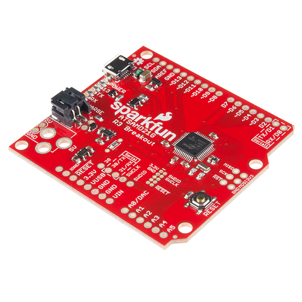
If you’re ready to step your Arduino game up from older 8-bit/16MHz microcontrollers, the SparkFun SAMD21 Dev Breakout is a great landing spot. The SparkFun SAMD21 Dev Breakout is an Arduino-sized breakout for the Atmel ATSAMD21G18, a 32-bit ARM Cortex-M0+ processor with 256KB flash, 32KB SRAM, and an operating speed of up to 48MHz. This dev breakout provides you with an Arduino hardware option that solves the problems of low storage limits and dynamic memory stack overflows that have plagued the previous iterations of the Arduino family. Yes, the SparkFun SAMD21 Dev Breakout is even fully supported in the Arduino IDE and libraries for the Arduino Zero!
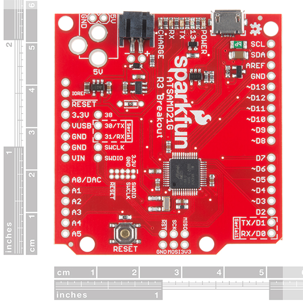
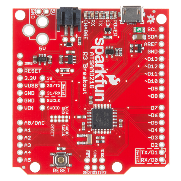
The SparkFun SAMD21 Dev Breakout has been equipped with a USB interface for programming and power, surrounded with an RTC crystal, and a 600mA 3.3V regulator. By utilizing the Pro R3’s extra PCB real-estate we've been able to leave room for a few extra GPIO pins and an integrated LiPo charger. To power the SAMD21 Breakout board, just plug it into a USB port on your computer via the micro-B port on the breakout. Not near a USB port? No problem, the SparkFun SAMD21 Dev Breakout is also equipped with a LiPo Battery connector (for a single-cell 3.7-4.2V litium-polymer battery) and unpopluated supply input to solder on your own PTH Barrel Jack (please be aware that the 3D model that we have on file does show a barrel jack attached, this is only for dimensional use since this breakout does not come with one attached). If you’ve used any Arduino before, this pinout shouldn’t surprise you – the layout meets the Arduino 1.0 footprint standard, including a separate SPI header and additional I2C header.
One of the most unique features of the SAMD21 is SERCOM – a set of six configurable serial interfaces that can be turned into either a UART, I2C master, I2C slave, SPI master, or SPI slave. Each SERCOM provides for a lot of flexibility: the ports can be multiplexed, giving you a choice of which task each pin is assigned.
The on-line SAMD21 Mini/Dev Breakout Hookup Guide (in the Documents section below) contains step by step instructions of how to connect your SparkFun SAMD21 Dev Breakout as well as a few circuit examples to test out. Full example code is provided and explained and even includes troubleshooting tips to make make you have zero problems.
Note: The breakout does NOT have headers or a 2.1mm barrel jack installed and will need to purchased and soldered on yourself. Check the Recommended Products section below for the type of headers we use in the Hookup Guide!
- ATSAMD21G18 32-bit/48MHz ARM Cortex-M0+
- 256KB Flash Memory
- 32KB SRAM
- 32KB of EEPROM (emulated in Flash)
- 30 GPIO Count
- 14 ADC Channels at 12-bit Resolution
- Analog-to-Digital and Digital-to-Analog Converters (ADC & DAC)
- Vin: 4.2V-6.0V for charger - otherwise 3.5V-6.0V
- VBATT: 3.7V Lipo
- VCC: 600mA @3.3V
- Arduino R3 Layout
- Integrated USB Controller
- Schematic
- Eagle Files
- Hookup Guide
- Graphical Datasheet
- Datasheet (ATSAMD21G18)
- GitHub (Design Files)
SparkFun SAMD21 Dev Breakout Product Help and Resources
RedBoard Turbo Hookup Guide
January 24, 2019
An introduction to the RedBoard Turbo. Level up your Arduino-skills with the powerful SAMD21 ARM Cortex M0+ processor!
SAMD21 Mini/Dev Breakout Hookup Guide
November 12, 2015
An introduction to the Atmel ATSAMD21G18 microprocessor and our Mini and Pro R3 breakout boards. Level up your Arduino-skills with the powerful ARM Cortex M0+ processor.
Adding More SERCOM Ports for SAMD Boards
February 4, 2019
How to setup extra SPI, UART, and I2C serial ports on a SAMD-based boards.
1 of 1 found this helpful:
**Connecting with the JTAGICE3 Programmer**
By wiring the the SWD pins from the JTAG adapter correctly, you can connect to the ATSAMD21G18A . The 2x5 JTAG adapter is not directly compatible with the 2x5 SWD pins on the dev boards. You would need to use jumper wires to connect to the respective pins listed in this table => [ http://www.atmel.com/webdoc/jtagice3/jtagice3.connecting_awire.html ].
Fuse Bits?
Viewing the fuses tab in AtmelStudio 6.2, here are the fuse settings for the SAMD21 Dev board:
NVMCTRL_NVM_LOCK = 0x00
NVMCTRL_PSZ = 0x03
NVMCTRL_NVMP = 0x1000
ADC_LINEARITY_0 = 0x08
ADC_LINEARITY_1 = 0x04
ADC_BIASCAL = 0x03
OSC32K_CAL = 0x3D
USB_TRANSN = 0x05
USB_TRANSP = 0x1D
USB_TRIM = 0x03
DFLL48M_COARSE_CAL = 0x21
DFLL48M_FINE_CAL = 0x200
ROOM_TEMP_VAL_INT = 0x1E
ROOM_TEMP_VAL_DEC = 0x00
HOT_TEMP_VAL_INT = 0x55
HOT_TEMP_VAL_DEC = 0x00
ROOM_INT1V_VAL = 0x01
HOT_INT1V_VAL = 0xFF
ROOM_ADC_VAL = 0xA99
HOT_ADC_VAL = 0xC8F
NVMCTRL_BOOTPROT = 0x07
NVMCTRL_EEPROM_SIZE = 0x07
BOD33USERLEVEL = 0x07
BOD33_EN = [ ]
BOD33_ACTION = 0x01
WDT_ENABLE = [X]
WDT_ALWAYSON = [X]
WDT_PER = 0x0B
WDT_WINDOW_0 = [ ]
WDT_WINDOW_1 = 0x05
WDT_EWOFFSET = 0x0B
WDT_WEN = [X]
BOD33_HYST = [X]
NVMCTRL_REGION_LOCKS = 0xFFFF

OTP1_WORD_0 = 0x10000300 (valid)
OTP4_WORD_0 = 0x40004007 (valid)
OTP4_WORD_1 = 0x85F4AF5C (valid)
OTP4_WORD_2 = 0xFFFFFE00 (valid)
TEMP_LOG_WORD_0 = 0x105501E (valid)
TEMP_LOG_WORD_1 = 0xC8FA99FF (valid)
USER_WORD_0 = 0xD8E0C7FF (valid)
USER_WORD_1 = 0xFFFFFC5D (valid)
Checking with our engineer and looking through the batch files, it appears that we do not modify the fuse bits like the Atmega328P microcontrollers.
1 of 1 found this helpful:
Windows failing to recognize board?
If Windows fails to recognize the board and gives a "USB Device Not Recognized." error, try a quick double tap on the reset button to force the board into bootloader mode, and then upload some known good code like "blink."
1 of 1 found this helpful:
Board dissappeared or turned into a Zero?
You can upload to this board with "Arduino/Genuino Zero (Native USB port)" selected in the IDE, however, it you do this the board will suddenly become an Arduino Zero under Windows and unless you have the Zero drivers installed, will then become an unknown device. If that happens, just install the Zero drivers located in the IDE folder and then upload any sketch to the board with "SparkFun SAMD21 Dev Breakout" selected and this will restore the board.
Core Skill: Soldering
This skill defines how difficult the soldering is on a particular product. It might be a couple simple solder joints, or require special reflow tools.
Skill Level: Noob - Some basic soldering is required, but it is limited to a just a few pins, basic through-hole soldering, and couple (if any) polarized components. A basic soldering iron is all you should need.
See all skill levels
Core Skill: Programming
If a board needs code or communicates somehow, you're going to need to know how to program or interface with it. The programming skill is all about communication and code.
Skill Level: Rookie - You will need a better fundamental understand of what code is, and how it works. You will be using beginner-level software and development tools like Arduino. You will be dealing directly with code, but numerous examples and libraries are available. Sensors or shields will communicate with serial or TTL.
See all skill levels
Core Skill: Electrical Prototyping
If it requires power, you need to know how much, what all the pins do, and how to hook it up. You may need to reference datasheets, schematics, and know the ins and outs of electronics.
Skill Level: Rookie - You may be required to know a bit more about the component, such as orientation, or how to hook it up, in addition to power requirements. You will need to understand polarized components.
See all skill levels
Comments
Looking for answers to technical questions?
We welcome your comments and suggestions below. However, if you are looking for solutions to technical questions please see our Technical Assistance page.
Customer Reviews
4 out of 5
Based on 7 ratings:
2 of 2 found this helpful:
Poor SAMD boards core support, ok hardware, there are better options.
I was reasonably happy with this board until my program grew to over 20k. Then it became impossible to program over native USB due to COM port dropouts. There's a known fix for this, yet Sparkfun hasn't updated their SAMD boards core or bootloader in months. This board relies heavily on the Zero toolchain, and as that is still relatively new and undergoing many updates and bug fixes, Sparkfun needs to keep up with them. Their customer/tech support was extremely disappointing - they replaced the boards which of course didn't fix the problem, then when that didn't work, just stopped answering emails. It's a shame because this could be a great product. As is, I'd recommend buying a Feather M0+ instead, as Adafruit is actively involved with the Arduino Zero development and keeps their toolchain up to date. I've had no problems with the Feather, I just wish it had more pins broken out.
Also, the battery charging circuit audibly rings during the last ~25% toward full.
Our boards core has been updated. Does this fix the issues you were seeing with uploading large programs?
Economical and well designed ...
Documentation very good, git hub has been updated, and I think there is no longer requirement for IAR to rebuild core, if I read makefile correctly.
Does anyone know where I can get the small header strip for the JTAG SWD connection. Seems like .05 mm spacing?
Thanks!
The SWD connection uses .05" spacing, and you should be able to find headers of that pitch over at Digi-Key.
Extremely well done breakout for SamD21
I wanted to step up to 32 bit microprocessors for my circuits, this breakout is so well documented to make this easy. Works well with the Arduino IDE and with Atmel Ice programmer and Studio 7.
So far it's fine
I have a linear quadrature encoder which the Arduino Uno can read just fine as long as the motion is slow enough. The SAMD21 reads the encoder at much faster speeds, as you would expect. The next project will be independently controlling the rotational speed of four dc motors while simultaneously reading five geartooth sensors. Further complexity may be the addition of four sensors to count objects as they pass by. Things I like: multiple serial tx rx hardware, real time clock, LiPo charger, fairly seamless use of Arduino code, support to integrate SAMD21 Dev board into IDE.
Connecting via Windows 10 Surface USB 3 Port
I tried initially an upload via the USB 3 port of the example program, after completing the given SAM device and Arduino setup. My uploads failed to complete for both the Dev and Mini boards. I then connected a USB 2 hub to my Surface Book's USB 3 port, and connected the board(s) to the USB 2 hub. Worked first try for each board! I am next planning to use the Atmel-Ice after installing the headed pins (ordered from the recommended vendor stated in the Sparkfun setup guide).
Very helpful for prototyping
I purchased this board to help with a commercial SAMD21 development project. I needed access to pins that other boards didn't make available (sercom2 flow control for example) and this board saved me from developing a custom dev board. I created a custom board variant for my project and was able to prototype all the interfaces necessary to prove feasibility. Even though the commercial project won't be based on Arduino, this board allowed me to take the first step.
Great, but...
This is a nice board but unfortunately there are still issues with it and its mini sibling uploading larger sketches. Using Arduino IDE 1.6.9, Arduino SAMD 1.6.5, and Sparkfun's SAMD 1.2.0 uploads of larger programs can stall. It's unfortunate that Member #532709's comments above state that it is a toolchain issue and there is/are known fixes but provides no links.
There are a few posts in the forums regarding slow upload speeds and these issues seem related. The posts suggest using a different USB cable, a USB hub, or a different USB port on your computer. I stumbled on these posts after spending hours pulling my hair out and can confirm that they solved my problem. For me it was switching from my laptop's USB 2 port to the USB 3 port. I can now successfully upload a 42 Kb sketch without stalling.
Edit: After a number of successful uploads, still having intermittent issues so while switching USB ports, etc. may help, it's not a sure fix. <sigh>
Keep this in mind as you move beyond your "Hello World" or "Blink" sketch and try to do something real, which is why you bought this thing in the first place.
Whoa! Arduino Zero is sold for $46.20 + VAT, which will be more than $56 overall. If I will ever decide to try this chip, I will pick this board. Especially when Arduino IDE does not support debugger.
Would love to see a SAMC21 version of this? 5V tolerance for the win!! Not sure when the chips will be available in bulk though.
Great design! Sparkfun did what Arduino should have done with the Zero.
Dear FFT (fast fourier transform) users, If I understand this correctly, the processor is a Cortex-M0+. Therefore, should it support the CMSIS DSP (digital signal processing) library? If so would it give much improved FFT processing speed over using the standard Arduino library?
Installing the Teensy 3 seems to do the job of getting the CMSIS DSP library installed, I think. However, calls to functions shown in the arm_math.h library are indicating an error in the Arduino compiler library. Does anyone have thoughts on making this work?
Does anyone have any insight into the best way to get an FFT function running on this board?
Ok folks... I must say... I priced the components at mouser and the board, with my modifications at oshpark and I must say... this is a great deal. Components, not including jst or usb jacks was $15. 3 boards at osh came to $8 a piece. That doesn't include stencil and solder paste and the risk of it not cooking right, and your time. These boards are a major deal! I'm just going to make a shield for it instead and buy these boards or recommend them for my open source project. My only issue is the RTC. Would be nice if the next iteration of this board had some accommodations for a coin cell battery to keep the RTC alive. No biggie though... this board looks like the way to go and will be ordering some when I get my shield designed out.
I believe I have found an error in the variant file for this board. This problem may have been corrected already as the variant file I am using is from January. The pin definition for the RX LED is mapped to the wrong register pin. In the variant file I have this as the line that is wrong: { PORTA, 31, PIO_OUTPUT, PIN_ATTR_DIGITAL, No_ADC_Channel, NOT_ON_PWM, NOT_ON_TIMER, EXTERNAL_INT_NONE }, // used as output only I changed it to this which appears to work: { PORTB, 03, PIO_OUTPUT, PIN_ATTR_DIGITAL, No_ADC_Channel, NOT_ON_PWM, NOT_ON_TIMER, EXTERNAL_INT_NONE }, // used as output only
Hi there, it sounds like you are looking for technical assistance. Please use the link in the banner above, to get started with posting a topic in our forums. Our technical support team will do their best to assist you.
If possible please link the variant file you are using in your post. Otherwise, are you referring to the Arduino core board definition file? If so, I don't think we have updated any of the files for that specific board in the board definitions for a while.
I want to try to burn the bootloader into SAMD21. Any tutorial?
It's been on my radar to write. I'll look into it.
I'm trying to use this board with Microsoft/SparkFun's makecode: https://makecode.sparkfun.com/ When I download the code from the website, it says "Press the reset button once on the SAMD21. Move the .uf2 file to the ARDUINO-M0 drive to transfer your code...". I don't see any ARDUINO-M0 drive, either in the Finder, or in /Volumes. The USB port does show up in /dev/tty.usbmodem1411, but copying the file to there does nothing. Any advice?
I added support to the Microsoft UF2 booloader for this board. See https://github.com/Microsoft/uf2-samd21 and https://github.com/Microsoft/uf2-samd21/pull/17.
You can build it with make BOARD=sparkfun-samd21-dev
I need to use SWCLK and SWDIO as general IO for a board. Is there a way to do this with this board using the Arduino IDE?
I bought SparkFun SAMD21 Dev Breakout and started using Arduino IDE.After 2 Days it Stopped working.Power Led is illuminating when i connected the usb cable and port is not detecting and i am unable to upload the program into it.I also tried troubleshooting methods given by Sparkfun but no use,its not working.Similar for my two same Boards.Can anyone help me to solve the problem.
Has anyone tried out the sampling frequency of the ADC on this board? I know the datasheet said that it's capable of 350ksps. I was just wondering if anyone has seen this first hand or if that was a theoretical sample rate.
Q: about the Arduino IDE -- has anyone figured out why the SamD boards are grayed out under Tools\boards in the 1.6.6 ? Adafruit had some answers about problem libraries, but not sure if it addresses this issue. Wish Nate had someone who was in charge of software issues.
Does this board have Debugging capabilities like the Arduino Zero?
If I design my own board with the SAMD21, can the Arduino bootloader be put on in the standard way with the ISP header and an ISP programmer? i.e. the same way an Atmega328 bootloader is added.
Kinda, sorta. You'll need an ARM programmer that's compatible with the SAMD chip (the Atmel-ICE, for example), and a different set of software tools to upload the code from your computer (Atmel Studio - and the included atprogram CLI work well if you're on Windows). But, yeah, aside from the different tools, it's pretty analogous to loading a bootloader onto the ATmega328.
Is USB host mode supported on either SAMD21 boards? I am using a Arduino Zero with a USB OTG to host cable + USB keyboard. The example USB keyboard sketch works great.
Can the same be done using either or both SAMD21 boards? Is the micro USB port equivalent to the Zero native USB port? How should be board be powered so it provides 5V USB output to the keyboard?
The schematic shows the micro USB ID pin and USB_HOST_EN are connected which makes me think host mode should work but I do not understand how the hardware works.
My understanding from the schematic is that USB host mode will work. The USB port on board is a microAB connector so it accepts microA and microB cables. It should operate like the native port on the Arduino Zero.
My larger question is... if you place this dev board into USB host mode can you use the native USB port to also re-flash a new Arduino sketch to bring it out of USB host mode?
Yes, host versus device mode switching is determined by the cable plugged into the native port so it does not matter what the sketch is doing. Plugging in an OTG to host cable switches the native port into host mode. Plugging a cable to a computer host port switches the native port to device mode for bootloading, console, etc.
Long answer
In the graphical datasheet, PA14 is marked as I2C-capable. However, the Atmel datasheet does not mark this pin as I2C-capable. (It seems no PAD2 or PAD3 pins are I2C capable, actually.)
You are correct. I blame it on my brain seeing things after staring at that datasheet for so long. I'll hopefully get it updated in the next week or so.
Howdy all! I am a little confused about setting up this board for Arduino compatibility.
Since the new Arduino IDE supports the Zero already, why would I need to install another arm tool chain, wouldn't the native Arduino compiler be sufficient? Also the Shumatech Basso avrdude "replacement" is not happy loading on Windows 10. I am in test mode so driver signing should not be issue, and I'm getting a silent installation failure. Is there an alternative?
Which libraries should I expect to work if and when I get you installation instructions noodled out?
Best,
R.
(Not that I'm complaining this is a great board!)
I did not have to install any of the three items in the first paragraph under "Install Arduino SAMD Boards", I just installed the board support in the Arduino IDE and everything worked fine from there.
(Meant to reply to your first comment, accidentally did this one. Whoops.)
I tried to use the ISR like the ONE : ISR(TIMER1_COMPA_vect) // timer compare interrupt service routine
but i receive this error:
exit status 1 expected constructor, destructor, or type conversion before '(' token
I will apreciate your help
Overriding the ISRs does not seem to work the same as other Arduino boards.
If you look at the Arduino SAMD source code, you can see that the vector table is filled with many named functions that (by default) are aliased to a dummy handler that loops forever. You can add a handle simply by defining a function with the name of the interrupt you want to use.
For instance, I made a handler for the SERCOM2 interrupt by defining a function like this:
Do all of the ADCs work with the Arduino IDE? As in all A0-A13, not just A0-A5.
Only A0-A5 are set up in the Arduino IDE. I'm not sure what you are referring to with A6-A13. If you check out the graphical datasheet you will see that about half the digital pins can be configured to work as ADC pins. But selecting the ADC functionality disables the digital functionality on a pin so they are not configured that way by default. If you need more ADC pins you can definitely configure 7 additional pins on the board (8 if you want to figure out how to connect an analog input to the RX LED) and name them however you'd like.
If anyone is looking for a debug header, part# 20021111-00010T4LF from FCI looks like a good candidate. Also, I highly recommend the Atmel-ICE debugger, for those going beyond the Arduino IDE. (copied from my post under the mini breakout).
I'm wondering if the 32.768kHz crystal is only used for the RTC? Would the board function without this crystal (minus RTC capabilities)?
If you check the schematic and datasheet, you'll note that the 32.768 kHz crystal is connected to the XOSC32 pins. This is a secondary input specifically for 32kHz oscillators, as the name implies. Ideally an external crystal for the primary clock would be connected to the XOSC inputs. However, I'm pretty sure they couldn't do that for compatibility reasons with the Arduino Zero. The Zero uses these pins as D2 and D5. So it's Arduino's fault, not Sparkfun's. Assuming you think it's a problem. Is it a problem? Meh. The FLL/PLL on the Atmel SAM chips isn't very good anyway in my experience.
That's an interesting observation.
I don't see why the board would not function without the external oscillator.
I'm curious to know why SFE chose to go with an external 32.768kHz crystal on this board. The SAMD21 has two 32.768kHz internal oscillators--both a 32.768kHz High Accuracy and a 32.768kHz Ultra Low Power (in additional to several other full-speed internal oscillators). Perhaps may more accuracy?
I'd like some info on the bootloader present on these boards, are you using the arduino zero code, or did you create your own, and if the later, where is the source? I'd also like the instructions for updating/replacing/repairing the bootloader should it get bricked.
I'm thinking of buying one of these boards, but actually I'd like to see a version based on the SAMD21J18 part (64 pin). That much flash and ram is just crying for more I/O pins, and a "MEGA" footprint version with this cpu would be nice. I'm kinda wondering how to hack together something like that myself, hence the bootstrap questions.
One more thing, 19K code just for the blinky sketch? True that's only 4% of the code space, but the same sketch on an AVR would be a LOT smaller. Where's the overhead?
I've added the bootloader source and our compiled binary to the GitHub repo.
It's a slightly modified version of the Arduino Zero bootloader (added some code to blink RX and TX LEDs, swapped in our VID/PID), which is based on Atmel's SAM-BA bootloader. That should be port-able to the SAMD21J parts.
With this breakout/bootloader is it possible to upload over one of the UART interfaces? If so, how does one go about doing this and which SERCOM port or ports does it work on? Is it possible to initiate a reset/upload using RTS as we currently do with the Pro Mini?
Uploading via USB is not an option for our use case, because the devices are going to be located in public areas and running USB connections to those areas is impractical and has problematic security implications. Since our code changes frequently, sending someone around with a laptop isn't an option either. For our existing Pro Mini-based generation of devices, we use RS-422 transceivers for uploading/communication, and we would like to keep it that way.
Thanks! - Aaron
The bootloader is designed to upload code over USB, but I see no logical reason why a bootloader couldn't be written to upload code over serial. Also don't forget the programming header on the board, although that might not work well with the RS-422 transceivers.
Can the bootloader be flashed with JTAG from an AVR Dragon or will I need to purchase an ICE programmer?
Unfortunately not. As cool as the Dragon is, it doesn't support ARM chips like the SAMD21.
Thanks for the info, went ahead and ordered myself an ATMEL ICE and it was well worth it. Far more stable than the dragon ever was for me.
Please please pretty please make a board like this for a chip that has a hardware floating point unit (such as the AT32UC3C or ATSAMG53).
My navigation filters and controllers would run so much faster with hardware floating point instead of emulated floating point!
"Shcematic" -- I'm guessing this is the British way of spelling this? :P
Great board! Definitely a good deal compared to the Zero.
Actually it's New-Zealand's spelling. The Brits just spell it as "schematic".
I like the connectors you have chosen for power and micro USB. Good added value! This is an affordable alternative to the Zero for folks who don't need EDBG support.
I don't like the fact that you made the board without the headers. Is there a chance that you can offer the full version as another SKU?