- Home
- Product Categories
- Raspberry Pi HATs
- SparkFun Qwiic HAT for Raspberry Pi

SparkFun Qwiic HAT for Raspberry Pi
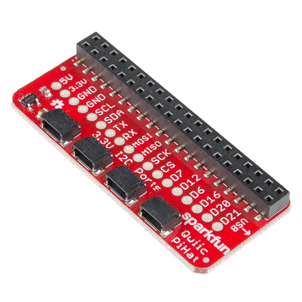
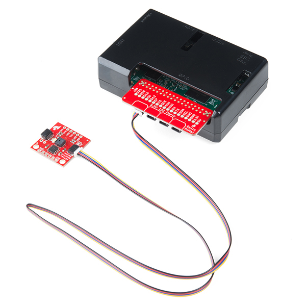
The SparkFun Qwiic HAT for Raspberry Pi is the quickest and easiest way to enter into SparkFun’s Qwiic ecosystem while still using that Raspberry Pi that you’ve come to know and love. The Qwiic HAT connects the I2C bus (GND, 3.3V, SDA and SCL) on your Raspberry Pi to an array of Qwiic connectors on the HAT. Since the Qwiic system allows for daisy chaining boards with different addresses, you can stack as many sensors as you’d like to create a tower of sensing power!
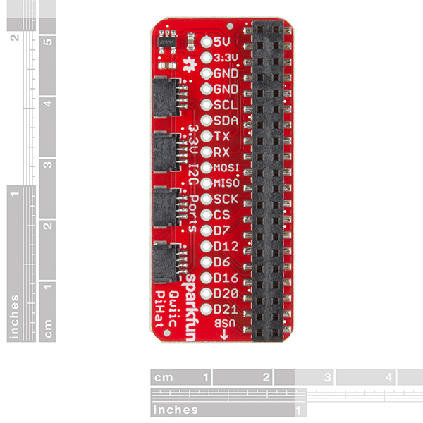
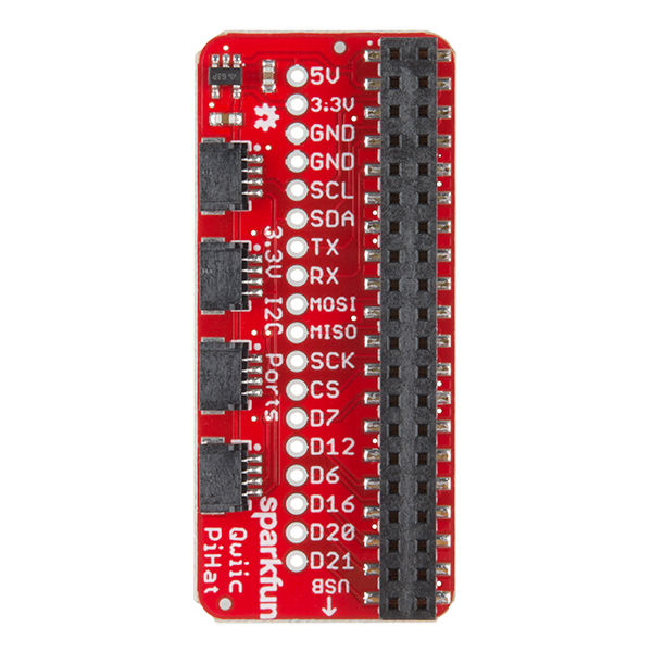
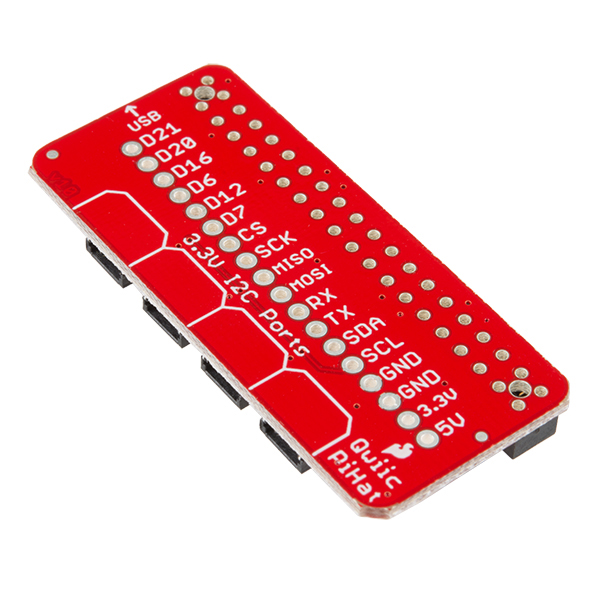
The Qwiic Pi HAT has four Qwiic connect ports, all on the same I2C bus. In addition, many of the useful GPIO pins on the Raspberry Pi are broken out. This HAT is compatible with any Raspberry Pi that utilizes the standard 2x20 GPIO header. It has been designed to sit to the side of the Pi, allowing it to work conveniently with a Pi Tin enclosure to connect boards to the Qwiic ports.
Note: There is a small silk error that has reversed the SDA and SCL. This is simply a cosmetic mix-up and will not impact any function with this board.
The SparkFun Qwiic Connect System is an ecosystem of I2C sensors, actuators, shields and cables that make prototyping faster and less prone to error. All Qwiic-enabled boards use a common 1mm pitch, 4-pin JST connector. This reduces the amount of required PCB space, and polarized connections mean you can’t hook it up wrong.
- 4x Qwiic Connection Ports
- Select GPIO Pins Broken Out
- Pi Tin Compatibility
SparkFun Qwiic HAT for Raspberry Pi Product Help and Resources
Qwiic HAT for Raspberry Pi Hookup Guide
November 30, 2017
Get started interfacing your Qwiic enabled boards with your Raspberry Pi. This Qwiic connects the I2C bus (GND, 3.3V, SDA, and SCL) on your Raspberry Pi to an array of Qwiic connectors.
Qwiic Magnetometer (MLX90393) Hookup Guide
May 3, 2018
Figure out how magnetic fields are oriented, all without having to solder a thing.
Qwiic Joystick Hookup Guide
February 21, 2019
Looking for an easy way to implement a joystick to your next Arduino or Raspberry Pi project? This hookup guide will walk you through using the Qwiic Joystick with the Arduino IDE on a RedBoard Qwiic and in Python on a Raspberry Pi.
Core Skill: Electrical Prototyping
If it requires power, you need to know how much, what all the pins do, and how to hook it up. You may need to reference datasheets, schematics, and know the ins and outs of electronics.
Skill Level: Rookie - You may be required to know a bit more about the component, such as orientation, or how to hook it up, in addition to power requirements. You will need to understand polarized components.
See all skill levels
Comments
Looking for answers to technical questions?
We welcome your comments and suggestions below. However, if you are looking for solutions to technical questions please see our Technical Assistance page.
Customer Reviews
4 out of 5
Based on 5 ratings:
1 of 1 found this helpful:
It's a nice little Hat to easily connect I2C devices to your project.
It was a snap to install getting my project up and running in no time. I was able to get any I2C device connected with the purchase of additional wired connectors. I plan to purchase more for other projects.
1 of 1 found this helpful:
I'm sold on Qwiic
I had a prototype that was pretty much an unmanageable tangle of "Dupont" wires. The PiHat fixed that and the prototype is running well.
I'll be back for more!
Two small complaints: a) Despite the Sparkfun video saying otherwise, my PiHat had to be installed hanging off the Raspberry Pi. b) Sparkfun's stock seems to be low on several parts and the extra shipping is annoying. The parts arrived quickly, but the cheapskate in me complained about the cost.
1 of 1 found this helpful:
Probably the most useful Pi hat
I like this hat better than the other PI QWIIC hats because it has additional breakouts for other pins as well. There is just one thing to note however, the i2c pins are miss labeled. SDA and SCL are backwards. I wish the other hats had break outs for other rPI pins as well.
2 of 2 found this helpful:
Great idea.. bad execution
Lets face it - The ENTIRE reason this thing exists is to make it easy to just plug and play some QWIIC devices, and expose some other pins on a header to connect some non-QWIIC devices..
I just wasted about 4 hours troubleshooting my project, which worked when connected to a breadboard, but failed completely when connected through this HAT. Certainly I must have made a mistake in wiring.. check, doublecheck, and only when I went DIRECTLY to test continuity to the GPIO header on the PI did I find out what I now realize another reviewer also mentioned.. A discrepancy in the SPI labels I was trying to hook up a MiFare RFID card reader which wants "SDA" to be connected to pin 24 (https://pimylifeup.com/raspberry-pi-rfid-rc522/) so naturally I connected it to the pin labeled SDA on this hat, but I find that pin 24 is actually connected to CS. I guess now it makes sense, because looking at a generic PI pinout, it does show pin 24 as an SPI chip select. This highlights what I know, but didn't think would come up in this situation - Each pin on a Raspberry pi can have different functions depending on how it's being used. Labeling this hat in this way is misleading, and although it's meant to be useful, it means I had to test continuity for each pin to make sure it was what I thought it was, regardless of the label.
In the next version of the board, I would recommend that instead of the function names, just label the pin numbers on the board, so that people can be SURE of what they're plugging into, and as a matter of fact - Why not just expose all 40 pins again, and let me stack another hat on top of this thing? In the space you have those few specific pins and their labels, you could put a 20x2 header (or just the holes, and let me solder one if I want) and then this thing would be WAY more functional, and the labeling wont be misleading.
I know that it really happened because the author of the MiFare driver decided to use non-standard pins (I guess in order to not interfere with i2c??) but in my hours of troubleshooting, it sure made it frustrating not to just have pin numbers on this board!
FWIW.. Now that I understand it, the board is working great, and I'm sure I'll use it again - I'll just have to reference the label to the pinout diagram (or just reference the schematic) to figure out what pin each header hole is connected to!
1 of 1 found this helpful:
Got two of these
I removed the regulator on one and jumped across the regulator pads to have +5V on the Qwiic power pins. Some boards are "non-standard" and needed 5V power with 3.3V I2C and this fit the bill with minor modifications. Used marker pin to identify which is which. Handy to have and more reliable then the shim boards if you are just talking to I2C from the pi.
Sorry but this is not a "HAT":
From: https://github.com/raspberrypi/hats "A board can only be called a HAT if:
It conforms to the basic add-on board requirements It has a valid ID EEPROM (including vendor info, GPIO map and valid device tree information). It has a full size 40W GPIO connector. It follows the HAT mechanical specification It uses a GPIO connector that spaces the HAT between 10mm and 12mm from the Pi (i.e. uses spacers between 10mm and 12mm). If back powering via the GPIO connector the HAT must be able to supply a minimum of 1.3A continuously to the Pi (but ability to supply 2A continuously recommended)."
No ID EEPROM, size is wrong, no mounting holes.
I like this hat better than the other PI QWIIC hats because it has additional breakouts for other pins as well. There is just one thing to note however, the i2c pins are miss labeled. SDA and SCL are backwards. I wish the other hats had break outs for other rPI pins as well.
I'd call it a breakout board. And I have a board made by Adafruit for the original Pi and in later nomenclature the people there call it a hat.
In fact since during development I typically use the serial port on the board (Pi) to confirm that the device properly started, especially when debugging a WiFi connection. Once I know it does work, I typically disconnect it. For the Pi3 it did need one.