- Home
- Product Categories
- Level Shifters
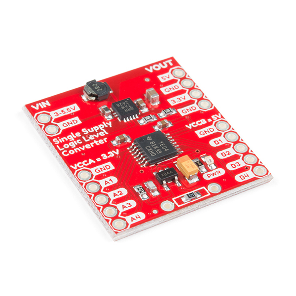
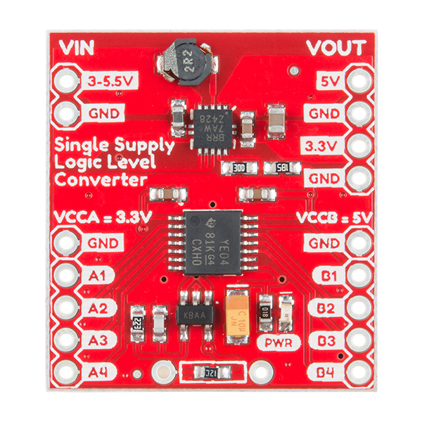
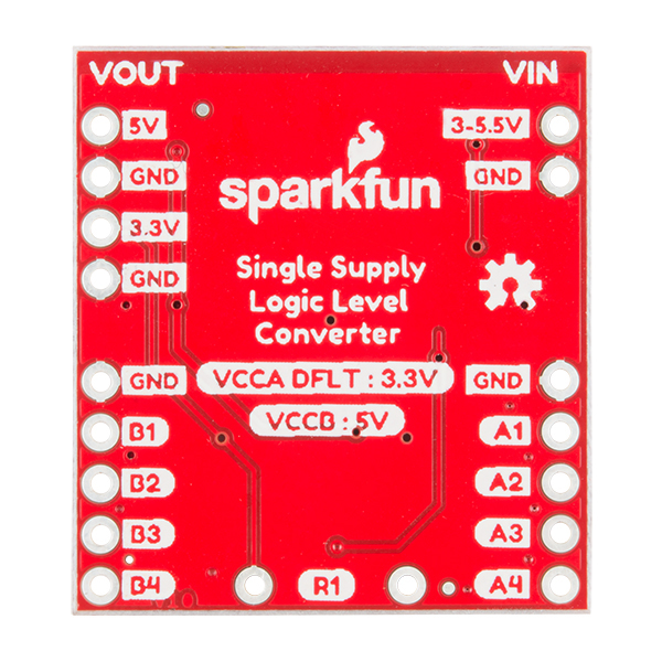
- SparkFun Logic Level Converter - Single Supply

SparkFun Logic Level Converter - Single Supply
The SparkFun Single Supply Logic Level Converter is logic level and power supply translator in one small package. This little board breaks out the Texas Instruments TXB0104 4-bit bi-directional voltage-level translator with automatic direction sensing. With this logic level converter you will be able to use your 5V logic microcontroller with 3.3V sensors without the second power supply!
What makes this Logic level converter truly special is the fact that you can supply it with 3.3V and it will create the 5V - meaning you can use your 3.3V system, and convert directly to another 5V sensor - and even power your sensor or other board!
This logic level converter provides 5V to the high side of the TXB0104 and the low side is programmable to 3.3V, 2.5V and 1.8V. Please keep in mind that the default low side voltage is 3.3V.
Note: This product does not work with Qwiic / I2C.
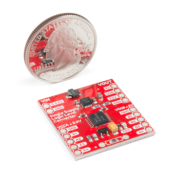
- Dimensions: 28.5mm x 26mm (1.12in x 1.02in)
- Schematic
- Eagle Files
- Hookup Guide
- Datasheets
- GitHub
SparkFun Logic Level Converter - Single Supply Product Help and Resources
Single Supply Logic Level Converter Hookup Guide
August 9, 2018
The Single Supply Logic Converter allows you to bi-directionally translate signals from a 5V or 3.3V microcontroller without the need for a second power supply! The board provides an output for both 5V and 3.3V to power your sensors. It is equipped with a PTH resistor footprint for the option to adjust the voltage regulator on the low side of the TXB0104 for 2.5V or 1.8V devices.
Core Skill: Soldering
This skill defines how difficult the soldering is on a particular product. It might be a couple simple solder joints, or require special reflow tools.
Skill Level: Noob - Some basic soldering is required, but it is limited to a just a few pins, basic through-hole soldering, and couple (if any) polarized components. A basic soldering iron is all you should need.
See all skill levels
Core Skill: Programming
If a board needs code or communicates somehow, you're going to need to know how to program or interface with it. The programming skill is all about communication and code.
Skill Level: Rookie - You will need a better fundamental understand of what code is, and how it works. You will be using beginner-level software and development tools like Arduino. You will be dealing directly with code, but numerous examples and libraries are available. Sensors or shields will communicate with serial or TTL.
See all skill levels
Core Skill: Electrical Prototyping
If it requires power, you need to know how much, what all the pins do, and how to hook it up. You may need to reference datasheets, schematics, and know the ins and outs of electronics.
Skill Level: Rookie - You may be required to know a bit more about the component, such as orientation, or how to hook it up, in addition to power requirements. You will need to understand polarized components.
See all skill levels
Comments
Looking for answers to technical questions?
We welcome your comments and suggestions below. However, if you are looking for solutions to technical questions please see our Technical Assistance page.
Customer Reviews
No reviews yet.
I need to know if the SparkFun Logic Level Converter - Single Supply (PRT-14765) can be used to directly control the speed of a PWM computer fan.
I have a 12V 4-wire PWM computer fan. (4 wires = 12V+, 12V-, 5V PWM signal IN, 5V RPM pulse signal OUT) I want to control the speed of the fan via it's 5V PWM signal input line. I am powering the fan with a 12V power supply that is separate and isolated from my Raspberry Pi. I would like to use the R-Pis HARDWARE PWM pin (not software PWM) to send PWM signals directly to the fan through the SparkFun Logic Level Converter - Single Supply since the Pi only outputs 3.3V, and the fan needs a 5V PWM input signal.
Is this possible to do ONLY using the SparkFun Logic Level Converter - Single Supply and NO OTHER extra circuit components? If so, do I need to connect a ground on the fan side or can I just use the single PWM input wire connected to the output side of the SparkFun Logic Level Converter - Single Supply? If I need to connect a ground from on the 5V side of the SparkFun Logic Level Converter - Single Supply, where would I ground it to? I wouldn't want to ground it to the 12V ground of the fan's power supply would I? Would I need to put resistors across the ground connection to the 5V ground of the SparkFun Logic Level Converter - Single Supply to make sure I'm not frying something? I could really use some advise on how to set this up... I thought this would be simple but it's turning into a nightmare just to control the speed of a fan that is already designed to be controlled by PWM signal input :-(
Thank you.
The voltage divider equation and provided values in the schematic are screwed up. The purpose of R3 is to clamp down the output voltage so it does not go above 3.6V when R1 is removed or not present.
If you want to put in a fixed value, then you need to remove R3 and either populate R3 (SMD) or R1 (thru-hole) with the value provided in the schematic.
If you want to add a switch selector for the input voltage, then you want to keep the R3 in place because during switching you may leave the circuit disconnected and the output will rail blowing the IC. Thus, what you want to do is replace R3 with 48.7K resistor, that way the default is 1.8V when the switch breaks before makes. Then add your switch in series with the following values in place of R1, ie parallel with R3: 1.8V = open/inf ohm 2.5V = 39.2K 3.3V = 18.2K
FYI, from the pictures R3 isn't 13K, it's 12K.
What is the advantage of something like this over some MOSFETs with pull-up resistors to handle logic level translation???