- Home
- Product Categories
- Sensors
- CMOS Camera - 640x480

CMOS Camera - 640x480
Replacement: None. We are no longer carrying this CMOS camera in our catalog. This page is for reference only.
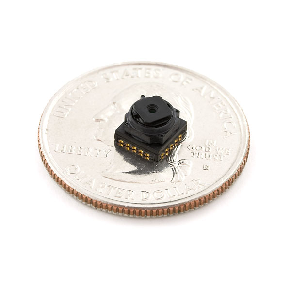
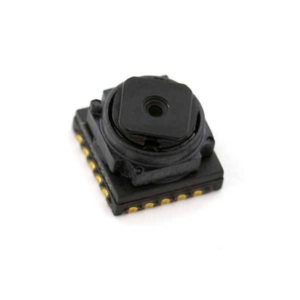
The TCM8230MD is a high quality, very small 640x480 CMOS camera from Toshiba with the standard data+I2C interface. The nice thing is that we have a complete datasheet on this camera along with a good supplier.
- Small size
- 2.8V Supply
- 30fps
- 640x480 pixels
- RGB color filter
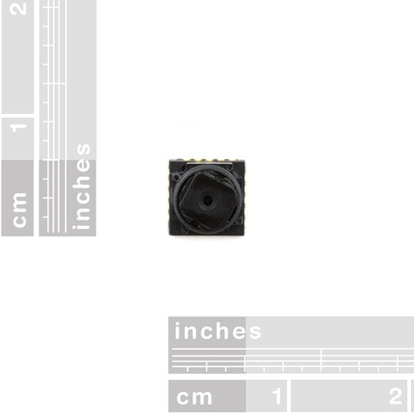
- 1/6 inch optics included
- YUV or RGB output
- Auto shutter control (AES)
- Auto gain control (AGC)
- Auto white balance (AWB)
- 6x6x4.5mm
CMOS Camera - 640x480 Product Help and Resources
Core Skill: Soldering
This skill defines how difficult the soldering is on a particular product. It might be a couple simple solder joints, or require special reflow tools.
Skill Level: Experienced - You might be required to do some reflow or basic rework with SMD components. A heat gun, Heaterizer or other tools might be required, and a good understanding of SMD soldering as well as PTH soldering are required.
See all skill levels
Core Skill: Programming
If a board needs code or communicates somehow, you're going to need to know how to program or interface with it. The programming skill is all about communication and code.
Skill Level: Competent - The toolchain for programming is a bit more complex and will examples may not be explicitly provided for you. You will be required to have a fundamental knowledge of programming and be required to provide your own code. You may need to modify existing libraries or code to work with your specific hardware. Sensor and hardware interfaces will be SPI or I2C.
See all skill levels
Core Skill: Electrical Prototyping
If it requires power, you need to know how much, what all the pins do, and how to hook it up. You may need to reference datasheets, schematics, and know the ins and outs of electronics.
Skill Level: Experienced - You will need to consult a datasheet for calculations to determine a components output format, linearity, and do a little math to get what you need. You will be using a datasheet or schematic beyond basic pinouts.
See all skill levels
Comments
Looking for answers to technical questions?
We welcome your comments and suggestions below. However, if you are looking for solutions to technical questions please see our Technical Assistance page.
Customer Reviews
No reviews yet.
I had a fabulousislybrilliantlyamazing idea!!!!!!!!!!!!! attach the camera output to a wireless module like an Xbee and then send the information through a microcontroller to a color LCD screen! you could even set the camera on an R/C helicopter for all I care
Why did this get a -1.4 rating! geez, it was only an idea for crying out loud
better?
Well I think my comment actually did deserve that rating, but I just wish Sparkfun had an option to delete comments because truthfully, I have no idea why I posted it. I should be giving feedback on the device, e.g. it should have a breakout board, but it's too late for that. Whenever I have an idea, I always have to say it SOMEWHERE, even if it's ridiculously stupid.
Trust us, we wish we could delete comments too ;-)
you probably would be limited by the data transfer rate. but whats wrong in trying? good luck.
You could also build a wifi security camera with the wifi xbee!
Need... breakout... board... (gasp)... (gasp)...
Breakout board available??
Breakout Board Please!
breakout board ??
This site has a breakout available:
https://www.base2.us/index.php?page=item&code=dev-toshcam-brkout
This guy made a breakout board as well. He got it to output to a sparkfun display and the schematics are included as well. The only thing I'm waiting on is for him to provide some code.
Is this the same as the TCM8240MD (note 8240 instead of 8230) in Sparkfun's Eagle part library?
Sorry to bump a 4 year old comment, but for the information of any others interested: Nope. Just checked: both footprint and pinout are incorrect. It takes little modification to edit one to the other, however.
I built a breakout board for this camera to use in a class on FPGAs I'm taking. I'd be more than willing to hand over the PCB design to SparkFun so they could sell the the breakout board.
Can I buy some breakout from you ?
Any chance you can share your design and what FPGA you used? I am trying to design break-out board that then goes to an FPGA and encodes the RGB to a motion JPEG or MPEG stream.
More information:
http://www.arl.army.mil/arlreports/2009/ARL-TN-344.pdf
This small one isn't too bad to read, but you need a fairly powerful microprocessor to get the data off in time. I hooked it up to an ARM Cortex M3 STM32: http://negativeacknowledge.com/2009/05/robot2-an-arm-based-colour-tracking-robot/
Essentially you just need to set the registers referred to in the datasheet to suitable values (only two really need changing) and then grab the data streaming off it.
The code I used is at http://github.com/randomskk/followingrobot which includes a short bit of inline assembler that reads each line of data.
For everyone else who clicked the link and found it was dead, I did some digging and found the code here: https://github.com/adamgreig/followingrobot
Even though this forum thread is for the other (higher-res) camera for sale, it sounds like noone really knows how to get this thing working, regardless of there being a breakout board available.
http://forum.sparkfun.com/viewtopic.php?t=10314
buyer beware
-e
How do i buy a sen08667 cmos camera?! What is the price?
Sorry, this product has been retired. We don't have any more of them in stock, and no longer have a source for them. :(
So I REALLY WANT A BREAKOUT BOARD just like everyone else. GUESS WHAT? Sparkfun, (love you so much now) made a breakout board for the TCM8240MD, and I downloaded the Eagle files and turned it into a breakout board for the TCM8230MD!!!
I was planning to use this handy dandy little cam for an add-on to my micro-quadcopter, but unfortunately, you can't attach this onto a PCB sideways, now can you? And @Sparkjoy Electronics, That was exactly what I was planning to do with this anyway. The only difference would be that I'm planning to use the AWESOMELY AMAZING NRF2LO1+ low power transceiver that only needs <12.5 mAh, and an ATmega32U4 for USB connectivity.
Molex has a plug for this to break it out to slightly more reasonable pins:
PN: 105189-0001 http://www.molex.com/molex/products/datasheet.jsp?part=active/1051890001_OTHER_SOCKETS.xml
But I can't seem to find it in stock anywhere....
Any idea on how to connect this to an Arduino?
Does anyone know where I can get a socket for this to go in, I cant find a proper one for the life of me.
is this camera used in nokia n70 front camera?
I want to connect this camera to N96 3.2 lcd. can I do it with connecting parallel pins of camera to lcd?
So um, anyone fancy the files of a breakout for homemade pcbs? :D http://img819.imageshack.us/img819/8118/8y89.jpg Still doesn't have the camera attached, but that will be done tomorrow.
Sparkfun please help me, I've been trying to get some useful information on how to use this camera with an arduino. Specifically the Due. How do you connect it to the arduino and get the picture data of the camera to store on a SD card??????? How do you handle data of the type over i2c?
thanks
If you look through the other comments on this page, you'll see that this level of component camera can be extremely difficult to work with. An Arduino really isn't powerful enough to deal with this complex of an interface. For your application, you might look into the JPEG camera and the related JPEG Trigger, which does exactly what you mentioned - use an Arduino-compatible board to take pictures and store them on an SD card.
BTW in case anyone is curious it's trivial to remove the lens from this camera. A pair of tweezers wedged between the lens and the camera will pop it right off. It's only secured with 4 dots of glue. Handy if you want to use your own lens.
I decided to use a DSPIC instead of a binary counter. This gives more flexibility for the counter design so there is no need for and gates and the like. Also the DSPIC can generate the CLK signal required by the camera.
Indoor UAV flying with them as the position sensors: http://www.youtube.com/watch?v=E4rtwI-eKTk
I figured this camera out for those of you who would like to work with a low speed PIC. I will post a tutorial soon, just note that it requires a few extra IC's These include a RAM chip, and a binary counter. This may sound complicated to a beginner but keep checking this product page and you'll soon see how simple it is.
If anyone wants to beat me to it, I'm using a 16 bit binary counter, a 4Mbit ram chip with 16 bit parallel address lines and 8 bit data lines, and a few AND gates, flip flops, etc so all the micro-controller has to do is read the RAM when it wants, and tell the camera to take a new picture when it wants. This can happen 30 times per second for video streaming or 1 time per hour for taking pictures, its up to you.
I'm excited to get this built because it allows us PIC users who don't use DEV boards to work with this camera, with little programming. My application is to use this camera to stream video over bluetooth using the WRL-08497 Bluetooth module from Sparkfun.
If anybody will find this useful, please feel free to comment. It will up my motivation to post a tutorial.
Again, don't be overwhelmed by AND gates and flipflops. They're as easy to use and understand as a transistor and I will explain them in a way that you'll slap yourself on the forehead for not using them in the past.
Cheers Sparkfun!
hey Vinnie, would you be able to give me a wiring diagram and a basic overview of how to connect this up to a low speed pic If any details need to be emailed i can send you my email adress
I just made a basic schematic which shows the logical concept for making this work with a DSPIC, though any old pic will work. The 4-input AND gate under the binary counter is set to turn on once the counter is > (6404802). The *2 is there because the camera spits out each pixel as 2 8-bit bytes, so you take the whole pixel array and multiply it by 2.
Don't forget you'll need at least a 6-8Mhz oscillator to drive the camera, which is not shown in this schematic. I'm using a PWM within the DSPIC to drive the CLK pin of the camera. The link to the schematic is here:
http://ryanbros.webs.com/Schematic_D01.jpg
Awesome! This is exactly what I need! Are there any considerations regarding the speed of the components or will any old CMOS do? Is it correct that the flipflop allows the address counter to be used for both reading and writing? But how do you ensure that the next recording will start at the beginning of a new frame? Is this controlled in software over the SPI interface? Also I don't see a 1.5V power line for the camera (pin 6, DVDD ). Is this to save space in the diagram or can it really be omitted? Sorry for the many questions, I'm rather new to this but love to learn :P
Hey sorry for the late response. I expected to get an email when someone replied but I must not have enabled that. I'm just starting this project this week and you have some very important questions. You will need a 1.5v line for the camera, which is not included in my diagram. The diagram in my link is only concept, its not an actual schematic so don't try to build it or you will have a broken circuit. In this scenario, the micro controller will reset the binary counter after every frame. I'm currently working on adding the extra 4 bits to the binary counter so I can count high enough to capture all 6404802 pixels. This will require some software but only enough to control the MS 4 bits (20 bits total). This is all still in the early stages but I'm glad you showed some interest.
Also, you can ignore the button cells and digital microphone. This schematic was made for a client so its got a few extras...
Happy soldering!
Found another link to seemingly good project using this camera. Sorry if this is duplicate. http://sigalrm.blogspot.com/2011/03/tcm8230md-breakout.html
Who wants a socket for this camera? We just got some in stock for a product we are working on that uses this camera and had to order more than we needed. It's far easier to solder and is oven/frying pan safe.
Hey there, if you've still got some of these I wouldn't mind picking one up. Or for that matter if you could even give me a part # or a trail to where any of us could pick one up. Thanks much.
I am quite interested in this camera, and keep seeing references to the socket. I am probably going to buy several of these, and would love to pickup some sockets. In fact, I would happily pay a few dollars more on each one if they were bundled together.
what socket is it exactly? One forum mentioned a "molex form-6" but, I have been unable to find that, or anything that even looks like the right thing from the molex website.
It surprises me actually that they are not offered here on sparkfun, it seems like exactly the sort of bundling that this store excels at. I don't come here because I know what part I need and want to order 1000 of them... I come here because I don't know, and want to pay a bit more for a model other people have had luck with, so I can prototype with some confidence.... sockets and breakouts are exactly the sort of thing I am looking for here.
I'm interested. How many do you have at what price?
I am workng on connecting this cmos camera on to a usb. Do i need a host for this cmos microprocessor or is there somehting else i can do.Any suggestions??
As hacromatic says, you need to convert the data into serial form. The camera has 8 parallel data lines out so you need to convert the parallel data to serial. I'm working on an FPGA board to do this using shift register designs. I guess I was more interested in digital design so I thought this camera would be a good challenge to try and grab data from using some custom digital circuitry. I'm working with a board that uses Altera's Cyclone III EP3C40 FPGA. It's pretty reasonable price ($80 a chip) considering other options, but might be overkill for you if you just want to use it for grabbing data.. (I was also planning to use this chip for other things later on).. Altera's site (and I'm sure Xilinx has good stuff too) has a few boards you might be able to look into with cheaper chips and an overall board cost of about $100. (http://www.terasic.com.tw/cgi-bin/page/archive.pl?Language=English&No=215) I think some of the boards also utilize USB and Ethernet, so you might be able to go that way.. Only problem with FPGA is you are getting into a totally different beast -> HDL, programming with company's IDE, etc. Pretty big learning curve for beginners but it is interesting stuff once you dive in.
G'luck n have fun!
What maximum resolution of camera the Cyclone III can process? By processing I mean capturing and doing simple actions like color correction and color tracking.
You can't directly attach the camera to USB, so you'll definitely need some kind of processor to wrangle the data from the camera into a serial form. The most direct approach is to use a beefy micro (say 80Mhz or faster) and catch the byte interrupts from the camera.
However, if you're comfortable with some assembly you can actually capture images from the camera using a plain ol' 8 bit AVR like the 8535. I started with this, and ended up using an AVR XMega so I could stay above the minimum clock of the camera.
I describe the approach I used for my Arduino shield over in the forum:
http://forum.sparkfun.com/viewtopic.php?f=5&t=10314&start=450#p146102
I don't want to give the impression that it's easy, just that it's possible, if you're a programmer and interested in a good challenge. A logic analyzer is also pretty much essential. I used the Logic 16 here on SparkFun and it worked great for this.
To get the data over USB you could use a micro with built-in USB, or transmit via serial to a USB module like the FTDI basic. Getting video is more work, and for that you'd likely want that beefy micro or an FPGA.
Are people still clamoring for a breakout board for this camera? At some point in the fairly near future I'll have a workable Eagle CAD component for this device that allows for hand soldering (if you can do surface mount by hand) and could easily make a breakout board based on this. Just let me know
thanks
Also, how did people design their soldering footprint? The schematic doesn't seem to give the dimensions for the reflow soldering footprint. I ended up using someone elses footprint for my design, but I would be curious to know how they designed it without it being present in the datasheet (yes I see the drawing on the last page, but that doesn't give the pads for soldering to the board (the places around the perimeter).
Thanks
Does anyone know what the typical current is that this thing draws? The data sheet says that peak current is 180mA, but this seems like an unacceptable value for most voltage regulators: (5-1.5)V * 180mA = .63W. Most of the voltage regulators I have seen that are reasonably sized usually have 215C/W, since .63 is being dropped over the regulator, it will be about 135C! That seems too hot because the shut off temperature is 175C... this really doesn't seem to leave much room for temperature fluctuation. So can someone give me some pointers as to what voltage regulators they used for their application or maybe what current they typically see the camera pull?
thanks!
I bought this camera but I am having a hard time to locate the pin number 1. I do not see any kind of cut on the side as shown on the datasheet. Can some body help me please?
Thanks!!!
Two things: If you look at the underside, there should be an extra bit of gold pad near pin 1. And on the uppermost outside ring, there is a nub coming off of it at the pin 1 position. You may need a magnifying glass for the second one.
Hi MikeGrusin
I am now able to find pin 1.I was really going crazy without it. Thanks for your help.
Why doesn't sparkfun sell a breakout board for this camera?!
This camera is 7 years old. Most modern ARM microcontrollers have a high speed interface for these cameras. I ran it from 1Mhz to 56Mhz, where it hit 70fps at 320x240. 1Mhz gives a brighter picture, at a speed suitable for 8 bit micros. The rolling shutter depends on clockspeed. Hot air reflowing it from on top melts the lens. Pointing it at the sun damages it, but it seemed to recover over many days.
Starting it required setting 2 registers: reg 0x3 = 0x4
reg 0x1e = 0x48
I have produced a 'breakout board' (litterally just pins to headers but provides a pcb footprint) in RS DesignSpark which should be convertable to EagleCad too. I also have gerber and drill ident files for the pcb.
Design files can be downloaded in a .zip folder here: http://alucinary.com/designspark_files.zip
Hi Perrint
Thanks for the design files. I am using those. Before I order my PCB just wanted to check whether you are able to use your breakboard. Is it working fine?
Thanks for the help.
Hi,
I use the term breakout board very loosely... it is literally just that - a way to more readily connect to the SM pins on the camera.
The pcb footprint however definitely fits as I made it up on a CNC milling machine with no issues and soldered the camera straight to it.
Glad it helped.
Hey Sparkfun why don't you buy image sensors like these: http://centeye.com/products/ardueye-shields-for-arduino/
they are fantastic!! And they are suitable for microcontrollers!!
I have this cam writing frames directly into an SRAM chip I pulled off an old hard drive. Which I then read with an ATMega.
Wrote up some info in the forums about it:
http://forum.sparkfun.com/viewtopic.php?f=5&t=10314&p=128344&hilit=TCM82#p136406
400kHz I2C bus with a fixed address requires me to have my bus operate at a glacial rate. If I want more than one camera, I have to use more than one bus because the I2C address is fixed. This sucks. Is there a better solution out there?
Can I use I2C for all data uses (ccontrol, picture data, etc.)? Also, has anyone successfully hooked this up to an arduino?
yeah, anyone got this working on an arduino?
Can anyone tell me if this camera can be used for IR night vision (if I light up the scene with IR LEDs) ?
Does anyone as a datasheet with all the registers explained on what they do?
It's been 3 years and still no breakout board. PLEASE make a breakout board for this camera Sparkfun!!
OMG breakout board please!!!!
Does any one figured out if the plastic nipple is the pin no.1 one? The datasheet is not very good on this subject.
CMOS Camera - 640x480; TCM8230MD
Guys, is there a software that is need to tlanslate the data into image in the computer ?
It will be a great help if some sone can guide in using this camera. thanks in advance
Jemmy
anyone know where I can find a chart showing the wavelength sensitivity for each color on this sensor?
Does sparkfun provide any kind of high volume supply? Or would it be possible to get information on where you are getting this module from?
1,515 of these things YES I think that is a very high volume supply
Would It be possible to only read the red value of each pixel? I'm having trouble understanding the datasheet, and I want to use this camera and a laser point for rangefinding.
I checked the data sheet to find out about the lens configuration, specifically the minimum distance that the camera can be from the subject, and also the depth of field ("focus range"). Both items were noted "TBD" (to be determined). Is there any more recent datasheets that might have this info? <br />
<br />
Unfortunately, that's all we have. We can try to get something better from the manufacturer, but I can't promise anything.
Actually I have an even better idea.
Use one of these puppies as a line buffer. There is still a timing issue here but the cpu can now read the data as it comes in, fall behind and catch up during the horizontal blanking interval. I need to check the timing, but it might work for QVGA at least.
http://focus.ti.com/lit/ds/symlink/sn74act7808.pdf
Continued ....
I don't think the xmega has enough horsepower to do mjpeg encoding in real time, but it might be possible to encode every second or third frame. You'd need several MB of external SDRAM to buffer the frames and hold the encoded jpeg or mjpeg. A block write would be used to copy the encoded data to the SD card. This could be prototyped on a hacked up Atmel Xplain board which already has the required SDRAM on it. You'd need to use the switch port as well as the two available free ports.
Ive been looking at the documentation for this and the Atmel Xmega processors. I'm almost certain that it would be possible to use the DMA feature of the xmega to read in the data. At first I thought that a large external memory array would be required to even capture the raw data to an SD card, but I forgot about the 'dead time' during the Horizontal blanking period. In CIF or QVGA mode there is enough time to store a line of data in SD flash(hsyncsel==1). In VGA mode it would take a fast SD card that could SCLK at > 8Mhz I think. You only buffer two scan lines and write one while reading the next. If you store the raw image data on the SD card it looks like an 8GB card will hold about 15 minutes of raw data at 15fps in VGA mode. You'd write to the card directly with no file system or partition table. You read the data out to a file on a PC (Linux dd). Then convert the raw data to jpeg, mjpeg or other format.
You might want to check this design with this cam:
http://forum.sparkfun.com/viewtopic.php?f=5&t=10314&p=109977#p109977
Does anyone create a Eagle layout for the breakout board yet?
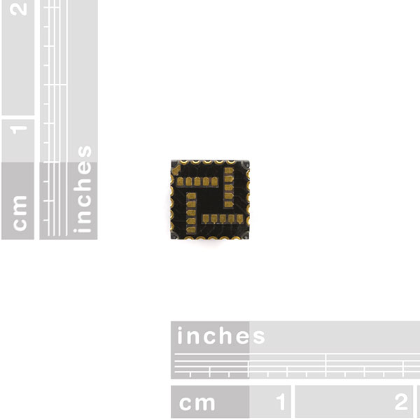
In the datasheet (on page 4) there is a diagram of the pin layout, which shows the 20 pins around the edges. What are the pads on the bottom surface of the camera? (Visible in the fourth picture above) Are they more pins, or duplicates, or nothing?
Hello there
I just got the camera that we hade ordered.
It seems hard to make any breakout board for it. I want to use it with zigbee.
Can you help me to find any breakout board or how can i buy any breakout board?
the camera module
CMOS Camera - 640x480
sku: SEN-08667
The pin layout in the datasheet is wrong, there is no flattened corner that denotes pin 1. The green sticker, that protected the lense, has a flattened corner, but can I rely on that?
There is a tiny piece of plastic at the ring of the lense, that I "guess" is pin 1. At least with that direction, I can measure "something" from pin 15 to all other pins. Pin 15 should be IOVSS (GND for I/O).
However, I would feel much better, if that would be clearer.
I just found that photo from Randomskk, there you can see the small plastic nipple with a green dot:
http://www.flickr.com/photos/randomskk/3225194149/sizes/l/in/set-72157607851550306/
how does the device output if you set it to W/B? does YUV give you 4bpp? RGB? Or something else entirely?
As far as i can tell, there is no Black and White mode....
On page 9 of the documentation, register 3, bit 0 lists as color mode. The options are zero for color or 1 for B/W, which I assume is black white mode. Does this bit do anything to the output?
you could do that part with software though.
Anyone got this camera up and running yet? I have soldered the wires to the camera, wasn't that hard, but haven't done any interface attempts yet..