- Home
- ADNS2620 Mouse Sensor Evaluation Board

ADNS2620 Mouse Sensor Evaluation Board
Replacement: None. This was an odd part and we ended up having difficulty keeping it in stock, so it's time for it to step aside and make room in the catalog for more cool new stuff! This page is for reference only.
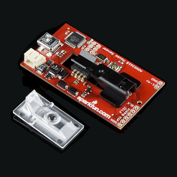
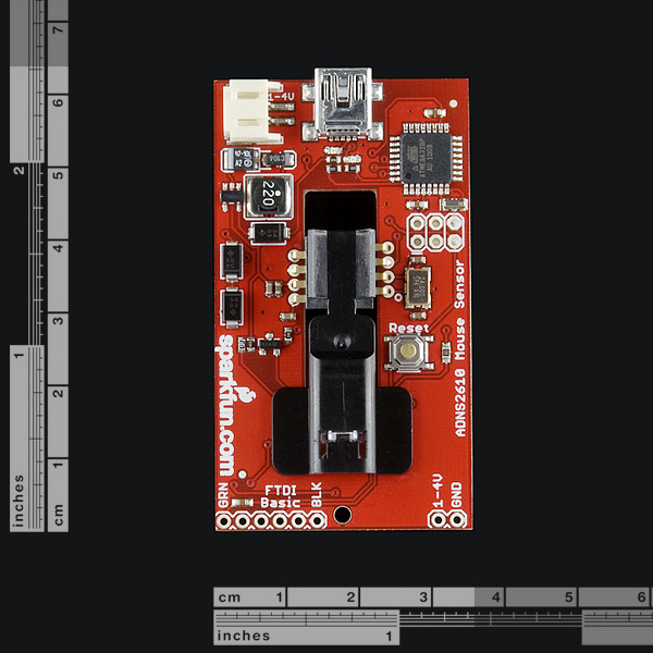
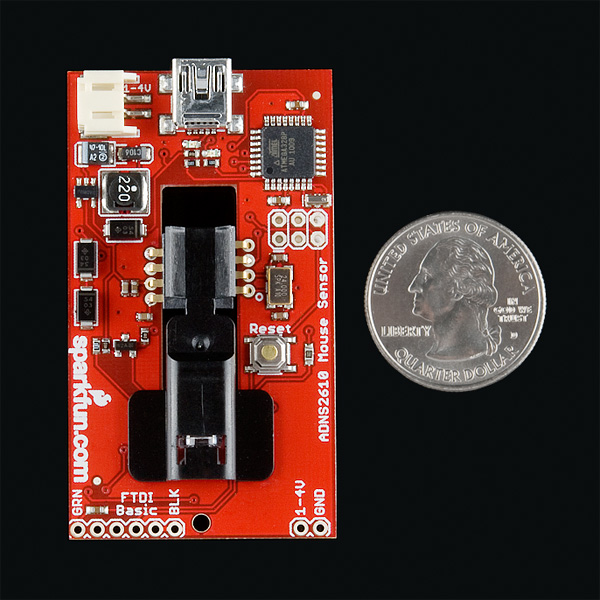
The ADNS-2620 is a small form factor optical mouse sensor. It is used to implement a non-mechanical tracking engine for computer mice. Now you can make your own optical mouse or input device.
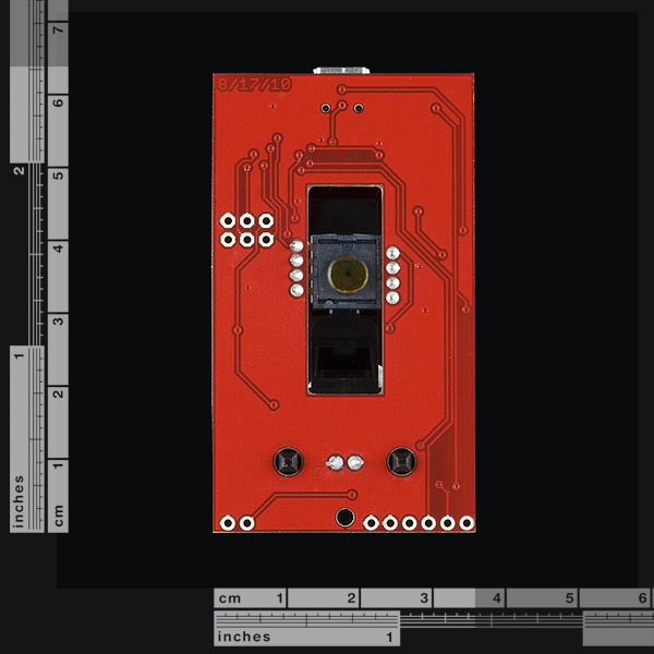
The evaluation board provides you with the necessary components to get started and some supporting circuity. Check the pictures for exactly what you're getting. You get a board with the IC mounted, top clip, bottom lens, and LED. In addition, it has a booster circuit for using a 3.7V battery for power. Also, we've included an ATmega328 preloaded with example code and an Arduino bootloader. We configured the AVR to act as an HID and therefore does not use an FTDI. For reprogramming and such, you will need an FTDI basic or similar. Plug in a USB miniB cable and this will show up and act like a mouse on your computer.
- Schematic
- [Eagle Files](http://www.sparkfun.com/datasheets/Widgets/adns2620 eval board v12.zip)
- Datasheet
- Datasheet (Optical Mouse Lens)
- Datasheet (LED Assembly Clip)
- ADNS2620 Arduino Library
- HID Code
- Additional Design Files
- Example Project
Comments
Looking for answers to technical questions?
We welcome your comments and suggestions below. However, if you are looking for solutions to technical questions please see our Technical Assistance page.
Customer Reviews
No reviews yet.
Hi guys, if anyone still wants a sensor board I currently have a kickstarter going for one https://www.kickstarter.com/projects/1747562424/adns-3050-optical-sensor It doesn't feature a microcontroller like this one does but it has everything else needed to use the sensor
It uses a ADNS-3050 sensor with a higher resolution than the 2610, I also have code and 3d models to make a mouse with it.
I think Sparkfun should have a mouse sensor. They are still useful for many motion tracking apps. Avago sold their mouse sensor business to Pixart (www.pixart.com). I'd recommend the ADNS-3050, ADNS-3080 or ADNS-3090.
Any Chance of something like this appearing again?
I found that if I wanted to rewrite the arduino bootloader to the onboard 328, the "Arduino Pro or Pro Mini (5V, 16 MHz) w/ ATmega328" was the Board closest in the Arduino IDE.
I believe there is a mistake in the example arduino sketch provided (ADNS2620_Example.pde). This line:
ADNS2620 mouse(18,19);
Should actually be:
ADNS2620 mouse(A1,A0);
at least that's what worked for me.
I've made a blog post including links to the source code to use this sensor for position hold for a quadcopter.
http://diydrones.com/profiles/blogs/quad-position-hold-with-mouse-1
Hello,
How did you work the module? I am trying to run this module with Ardunio IDE but Ardunio IDE boards section is not include that module? How will you suggest a way which running this module ?
Best regards.
Win7 doesn't recognize this board as a mouse -- I get an 'unknown device' error, says device gives code 43. Any ideas as to how to deal with this?
Thanks.
I have the same issue with windows7 not recognising it as a mouse..
I found (with my own variation on this board), that I had to add zener diodes to clamp the D+ and D- lines to 3.3V for the mouse to be recognized (on some PCs). I believe the USB specification calls for 3.3V.
Hello there and merry Christmas!
I would like to ask the following questions:
1) Is it possible to use on Analog/Digital input of the arduino?
2) Is it possible to use on PWM pin of the arduino?
3) Can you recommend optics for further distances?
@kostal, I've picked up some lenses from this place that I hope to attach for furthe distances:
http://peauproductions.com/store/index.php?main_page=product_info&products_id=2
you'd also need a lens mount: http://peauproductions.com/store/index.php?main_page=index&cPath=25
no idea this would actually work - it's just an idea
It should! Please let us know how it turns out.
Some additional docs you might find helpful:<br />
<br />
The HDNS-2100 Lens Spec Sheet<br />
The HDNS-2200 LED Clip Spec Sheet
Good stuff. I added those both above, thanks.
I just picked up a couple of these to experiment with, and I'm having trouble getting them to work reliably.<br />
<br />
The main problem seems to be getting the lens positioned correctly. The black plastic LED clip seems to be positioned about 1mm too close to the chip and so I can't get the lens to fit over the sensor correctly.<br />
<br />
I've been measuring various board features using my calipers, and it seems like pin 8 was used as the layout reference point rather than pin 1, as indicated in Fig 3, Pg 3 of the ADNS-2620 data sheet.<br />
<br />
Has anybody gotten the lens properly positioned?<br />
If so, what did you do?<br />
<br />
Thanks,<br />
- Dean
Wait, USB HID done directly on an Atmega328? Am I missing something? Why doesn't this get used instead of an FTDI chip normally?
Yep, check the schematic. For just showing up as an HID the ATMega328 serves the purpose, but you still need an FTDI for passing code to the chip. It's not an all purpose solution.
Why not flash the USBaspLoader onto the chip and do away with the need for an FTDI breakout? You've got everything you need there except a dedicated pin for selecting the upload mode. You can probably use one of B3..5 to trigger the bootloader to run the USBasp emulator code rather than jumping to the user code or maybe someone can/has patched USBaspLoader to run on a timeout like the Arduino does.
I'm tempted to pick one of these up or one of the plain sensor breakouts to use as position/motion feedback on an XY table, but I have enough projects as it is.
Psh, how else are we going to sell everyone an FTDI basic? Come on, margin margin margin!
Kidding. But that's a good idea, maybe next rev.
There is already an open-source project to do the low-res mouse scanner thing (in fact I think more than one). Problem is it is a crude debug mode, not a proper camera so you can only get one pixel per update cycle and it takes about one second to read all 300-some pixels. So you can't really move it at all, or the image is smeared.
@jbeale - are you talking about this?<br /> <br /> http://spritesmods.com/?art=mouseeye<br /> <br /> It's cool to see an arduino version - but it seems from his page that you might not need the arduino to get the image out of the mouse if you wanted to make a scanner. <br /> <br /> My two cents: I'd rather have an option to buy the kit with a lens that was focused to infinity than focused for mousing� it would have more interesting applications (for me, not saying it would be better for everyone)
I also would like to see an infinite DOF focused lens.
I would like to use it to track my robots absolute movements over a surface
Why not revise the board with holes for mounting a standard CMOS/CCD lens mount? With a known tracking surface distance (or sensed) it should allow whatever dof you can find a standard lens for. One would have to account for the added zoom as a result of the tiny sensing area
Glancing at the data sheet it looks like the pixel data is available. That opens up the possibility of using it as a low resolution gray-scale scanner. (18x18 pixels, 64 shades of gray) You could use it as a bar code scanner, OCR, or have a robot sense the type of surface it's moving across. Combine the pixel data with vector data to assemble a much larger image.
I noticed that too. It seems like you might be able to use this for relative tracking (like mouse movement) as well as absolute tracking by looking for specific patterns (kind of like small 2D barcodes).
This would let you put a few symbol stickers on a table surface and a robot could hunt for those stickers and interpret meaning from them (like "I can charge here").
You could probably also implement a combination of motion feedback and line tracking using one of these.
clever hardware mounting
+
USB-to-Midi Software implementation
+
Custom Slipmat through Ponoko
Cheap Turntable Scratch-Controller?
You might think about doin' it, I am, lol.
no left click and right click buttons? I am disappoint