- Home
- Product Categories
- Development Tools
- CMUcam v4

CMUcam v4
Replacement: None. We are no longer carrying the CMUcam in or catalog. This page is for reference only.
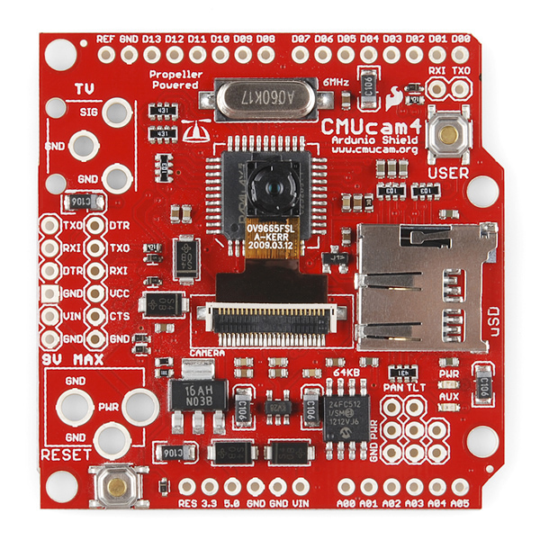
Computer vision is seriously cool technology but it takes a lot of processing power, it'd be nice to give your next microprocessor project the power to identify motion and color, but something like an Arduino would struggle to keep up. What you can do is have a dedicated processor do the heavy-lifting and then pipe that data to the Arduino, and that's exactly what the CMUcam4 does. The CMUcam4 is a fully programmable embedded computer vision sensor. The main processor is the Parallax P8X32A (Propeller Chip) connected to an OmniVision 9665 CMOS camera sensor module.
The CMUcam4 can be used to track colors or collect basic image statistics. The best performance can be achieved when there are highly contrasting and intense colors. For instance, it can easily track a red ball on a white background, but it would be hard to differentiate between different shades of brown in changing light. Tracking colorful objects can be used to localize landmarks, follow lines, or chase moving beacons. Using color statistics, it is possible for the CMUcam4 to monitor a scene, detect a specific color, or do primitive motion detection. If the CMUcam4 detects a drastic color change, then chances are something in the scene changed. Using “line mode”, the CMUcam4 can generate low resolution binary images of colorful objects. This can be used to do more sophisticated image processing that includes line following with branch detection, or even simple shape recognition. These more advanced operations require custom algorithms to post process the binary images sent from the CMUcam4. As is the case with a normal digital camera, this type of processing might require a computer or at least a fast microcontroller.
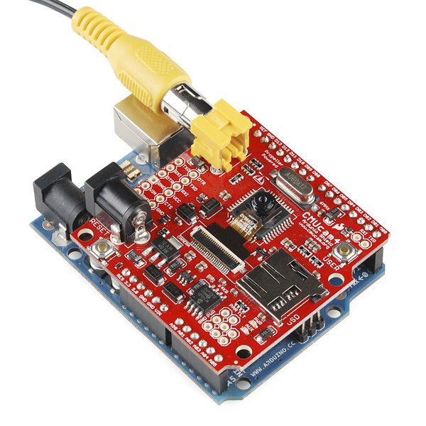
The most common configuration for the CMUcam4 is to have it communicate to a master processor via a standard TTL serial port. This “master processor” could be a computer (through USB or RS232), Arduino, Basic Stamp, PIC, or similar microcontroller. The CMUcam4 is small enough to add simple vision to embedded systems that can not afford the size or power of a standard computer based vision system. Its communication protocol and baud rate is designed to accommodate even the slowest of processors. For even slower processors, the CMUcam4 can operate in “poll mode”. In this mode, the host processor can ask the CMUcam4 for just a single packet of data. This gives slower processors the ability to more easily stay synchronized with the data. It is also possible to add a delay between individual serial data characters using the “delay mode” command. Due to communication delays, both poll mode and delay mode will lower the total number of frames that can be processed in one second.
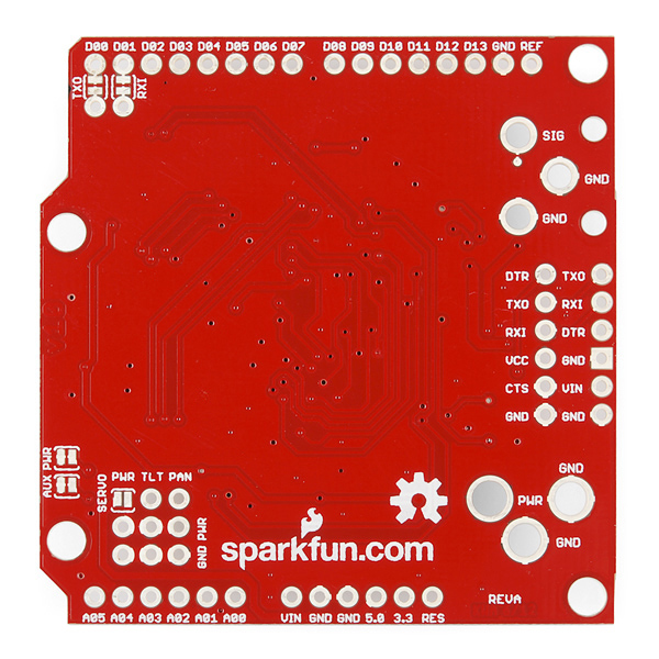
The RCA and barrel jack aren't populated because the connectors can affect the field of view when mounting the unit in an enclosure. Also, the servo power bus is disconnected in its default state, you will need to close the 'Servo EN' jumper on the back side of the board to enable power to the Pan/Tilt servos.
To program the Arduino with the CMUcam shield connected, you need to either use the 'HALT' feature, or disconnect the serial jumpers (SJ4 and SJ5), connect the two pin header (J1) to any digital Arduino pins, and then use the SoftwareSerial library included in the Arduino installation.
**Note: **A portion of this sale is given back to Carnegie Mellon University to help fund continued development of the CMUcam project.
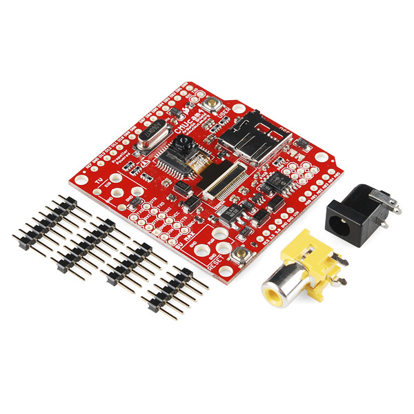
- CMUcam V4 Board
- RCA Video Jack
- DC Barrel Jack Connector
- 2 x 6-pin Straight Headers
- 2 x 8-pin Straight Headers
- Fully open source and re-programmable using the Propeller Tool
- Arduino Shield Compatible
- w/ Supporting Interface Libraries and Demo Applications for the Arduino and BASIC Stamp
- VGA resolution (640x480) RGB565/YUV655 color sensor
- Image processing rate of 30 frames per second
- Raw image dumps over serial or to flash card
- (640:320:160:80)x(480:240:120:60) image resolution
- RGB565/YUV655 color space
- Onboard Image Processing (QQVGA 160x120)
- Track user defined color blobs in the RGB/YUV color space
- Mean, median, mode and standard deviation data collection – sampled from a 40x120 resolution
- Segmented (thresholded) image capture for tracking visualization (over serial or to flash card)
- 80x60 image resolution
- Monochrome color space
- Histogram generation (up to 128 Bins) – sampled from a 40x120 resolution
- Arbitrary image clipping (windowing)
- µSD/µSDHC flash card slot with FAT16/32 full file system driver support
- w/ Directory and File manipulation
- I/O Interfaces
- Two-port servo controller (pan and tilt w/ 1us resolution at a 50 Hz refresh rate)
- Pan and/or Tilt servo channels can be configured as GPIOs
- Indicator user controllable LED (red) and power LED (green)
- TTL UART (up to 250,000 baud – 19,200 baud by default)
- Monochrome baseband analog video output (NTSC/PAL) of 160x120 resolution for tracking visualization (segmented (thresholded) image w/ color centroid and bounding box overlay at 30 FPS)
- CMUcam4 GUI for viewing images on the PC
- Project Page
- [Board Pinout](http://cdn.sparkfun.com/datasheets/Sensors/LightImaging/CMUcam4 Arduino Shield DOC BL&P - Rev A.pdf)
- Arduino Library
- Arduino Library Guide
CMUcam v4 Product Help and Resources
Core Skill: Soldering
This skill defines how difficult the soldering is on a particular product. It might be a couple simple solder joints, or require special reflow tools.
Skill Level: Noob - Some basic soldering is required, but it is limited to a just a few pins, basic through-hole soldering, and couple (if any) polarized components. A basic soldering iron is all you should need.
See all skill levels
Core Skill: Programming
If a board needs code or communicates somehow, you're going to need to know how to program or interface with it. The programming skill is all about communication and code.
Skill Level: Rookie - You will need a better fundamental understand of what code is, and how it works. You will be using beginner-level software and development tools like Arduino. You will be dealing directly with code, but numerous examples and libraries are available. Sensors or shields will communicate with serial or TTL.
See all skill levels
Core Skill: Electrical Prototyping
If it requires power, you need to know how much, what all the pins do, and how to hook it up. You may need to reference datasheets, schematics, and know the ins and outs of electronics.
Skill Level: Rookie - You may be required to know a bit more about the component, such as orientation, or how to hook it up, in addition to power requirements. You will need to understand polarized components.
See all skill levels
Comments
Looking for answers to technical questions?
We welcome your comments and suggestions below. However, if you are looking for solutions to technical questions please see our Technical Assistance page.
Customer Reviews
No reviews yet.
Alternative solution: RaspberryPi + $4 webcam + OpenCV I'm all for Arduinos, but sometimes it's worth moving to a more powerful platform.
Depends on what you are trying to accomplish. The level of effort involved in getting an RaspberryPi/webcam/OpenCV config up and running is far more significant than getting this CMUcam4/Arduino config up and running. On the flip side, the capabilities of the Pi setup will be far more significant than the Arduino setup as well.
Keep in mind, this board is more of a Propeller board than a Arduino board, IMO. The fact that it is in Arduino form factor just means it will be compatible with more hardware. There is a serial API and a Prop plug on there so you can reprogram the Propeller and use it stand-alone, so if anything, it is a Propellar dev board, in arduino form factor, with a serial API. Much different than a SBC with webcam. Also, the 30fps can only be realized on an Arduino if you manage your RAM well, so other processors are welcome. But for most purposes, the Arduino works just fine.
You can even take it one step forward and go for a beagle board, their processing capabilities are significant to both. though I admit i'm so fond of me mega board I usually just connect everything to the arduino and just ship the data to be processed elsewhere - which works fine for everything but video (and high rate data).
You know, there is a typo just under the CMUcam4 line on the upper side of the board. Silkscreen shows "Ardunio shield", does that mean that they changed their trademark? :)
Could you add this to the links above? http://cmucam.org/attachments/download/636/CMUcam4-Command-List-102.pdf (Command set)
The design purpose of the CMUcam4 is to interface with an Arduino and to add computer vision to an Arduino so that anyone who wants to learn work with simple computer vision can get started using their Arduino.
There are much more powerful alternatives. However, these all require you to move from working on your Arduino over to another platform.
Let's say you want to add a camera to some robot you are building to track some colored object. You could add a computer or Raspberry Pi, then attach a web cam, then write vision processing code, then figure out how to attach that computer to your Arduino, then figure out the Arduino code, and then finally make your application go.
But, if you just want to program your Arduino and nothing else then the CMUcam4 streamlines the process. If you don't care about Arduinos then get a Raspberry PI and do whatever you want to do.
Does this shield mean we are one step closer to building our own Mars Rover?! :-)
Excelent. I love when Sparkfun begin to talk about computer vision.
The camera on my CMUcam4 detached from the top of Propeller MCU (maybe due to warming of MCU?) And now I'm wondering should I use super glue or bubble gum to attach camera back?
Hi there, I wonder who's friend as you hear of our boards very early. Anyhow check http://silicam.org/welcome/?page_id=69 as we are giving a IGO for free every month for people to play and see the cool things that can be done on it.
I found an alternative it is called Silicam IGO, it looks interesting, anyone know if it will be sold in Sparkfun? According the specs it has two low resolution image sensors and can go up to 100fps, I received a flier from a friend but in their website (www.silicam.org) there is nothing yet. Anyone as info about it?
http://silicam.org/images/flier.pdf
is this camera compatible with the orangutan svp 1284?
Never thought i see the day.. Propeller and Arduino together. Can we call it Fankenduino??
Just got this soldered on. Some notes:
-It takes 10 seconds to save one picture at highest resolution. The image is sometimes weirdly distorted. -You often can't upload your program to device anymore. It fails maybe 80% of the time. -The Arduino IDE serial monitor quickly locks up when running with the camera and you may have to force quit frequently if you leave it open for too long -You can't really use Serial.print anymore, so any kind of debugging is difficult -Using Camera::printLine (to a file) is flaky and frequently doesn't write what you send out, making debugging even more difficult
All in all, it's a great idea and simple interface, but I wish I'd waited for a revision before spending $100.
Please check out the arduino interface doc.
You can't program your Arduino and use the shield or serial monitor at the same time. The shield uses the TX and RX lines, so does the arduino to communicate over USB. So what you are experiencing is bus contention. You either need to move the shields UART lines to softserial lines, use the HALT feature on the camera, or just remove the shield to program.
Also, be aware, if you use an arduino and and are running a lot of code, you can run into RAM problems. All of this is talked about in the arduino interface doc.
The code is fairly small (~25 lines) and has only the camera, histogram8, and a 100 byte string defined, so RAM probably isn't the issue. Thanks for the reminder, though :)
All the issues you mentioned are clearly talked about in the documentation. The CMUcam4 is not designed to take pictures. The picture taking functionality is simply for debugging purposes so that you can figure out the color you want to track. It's not a point and shoot camera. The reason the image is distorted is because the image is built out of multiple lines of consecutive frames. This means you can only take images looking at still objects in stable lighting.
Once you take an image you can figure out what color you want to track using the eye dropper tool in MS Paint for example. You can then feed that color back into the camera to track. Once you do this you can start to track colors really nicely.
Picking the color you want to track is the hard part. You can switch to YUV mode to get around lighting problems that come with using RGB mode.
The CMUcam4 is much easier to use with an Arduino Mega because you have multiple serial ports.
Thanks,
I forgot to mention: If you want to contact the developers directly, they should be able to answer your more technical questions. You can post on the forum, here.
Seems like a cool product, but for me it has a huge problem: the camera is mounted on the board which then attaches to and Arduino ; this assembly is way too heavy for a fast pan or pan&tilt servo setup.
If the camera used a separate tiny board with a cable to the shield (video, G, V+ ideally) I would get one right now. To pan/tilt this on a minimal bot is just too much of a pain.
The CMUcam4 has a built in PD control loop for doing pan and tilt. http://www.youtube.com/watch?feature=player_embedded&v=ByGZRh62glw
You don't have to connect the Arduino to the back of the CMUcam4. You can just attach RX, TX, PWR, and GND wires and you'll be good to go.
Regular servos respond slowly, however, some digital servos would likely be needed to work really fast.
Are the dimensions listed anywhere? Also, would this track an IR LED?
There's an IR filter on the camera so that it can track colors outside - this means it won't be great for IR. Please go to the CMUcam website www.cmucam.org for all the details.
am I missing something here or am is this just a bit over priced and underpowered for what it does? seems a usb webcam, a raspberry pi, and OpenCV ought blow this out of the water for much less. Maybe half the money.
Yea, you can probably get a setup that does a similar thing for much less $$, but the benefit to this board is that it is small enough to embed in your project and it is overall very simple to use and setup, out of the box. Also, I wouldn't call the Propeller on there underpowered, IMHO.
Dang..you guys beat me to it. I was hoping you guys would take some more time to release this module, so that I could finish the module I am working on.
Here is sparkfun thread regarding the project https://forum.sparkfun.com/viewtopic.php?f=14&t=32645