- Home
- Product Categories
- Development Tools
- Power Driver Shield Kit

Power Driver Shield Kit
Replacement:DEV-10618. The new version of this board has a protection diode on the power input. This page is for reference only.
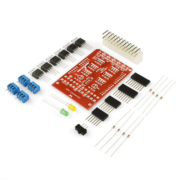
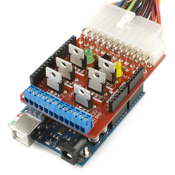
This shield allows you to use a computer power supply (or other power source) to use your Arduino to switch high current. With RFP30N06LE MOSFETS, you can easily control a lot of current directly from your Arduino.
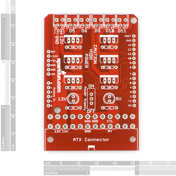
The board provides 6 PWM outputs via screw terminals. Check the datasheet for the MOSFET below for full specifications on how much current this board can handle.This board is a very easy way to start using MOSFETS for your next high current project.
Note: If you want to stack another shield on top of this one, you will want to double-up on the stackable headers to clear the MOSFETs.
- Schematic
- Eagle Files
- Datasheet (RFP30N06L)
Comments
Looking for answers to technical questions?
We welcome your comments and suggestions below. However, if you are looking for solutions to technical questions please see our Technical Assistance page.
Customer Reviews
No reviews yet.
Does this shield power up the arduino itself too?
I would make the following changes if this was re-designed for another revision.
jumper to choose between powering the arduino off the 5v or 5vsb of the ATX PSU (or left off to leave it powered seperatly) and another jumper to enable connecting the green turn on wire to a pin of the arduino to allow the arduino to power the PSU up when required, and turn it off when not.
URGENT: Can I control the LED Bars with this WITHOUT frying the bars?
Please help meh!
iam trying to make a led chess board using 64 rgb(or is it rbg) leds. i only need to have two banks for the leds. ie one for the black squares and one for the white squares. i got all my coding done already and ive been stuck trying to figure out how to power two banks of of 32 tri color leds.
ive tested all my code using all 6 pwn pins on my uno and one for the common ground. would i be able to use this board .
Anyone try using this as a charge/dump controller for wind or solar power. I plan to try and use the Ardy to switch between multiple battery banks and hope this will do the trick.
so if i hook this up to my arduino and a PIR motion sensor and did some computer modding could i use this to turn on my pc with out touching it like could i use this as a switch with the pir as the switch and the arduino as the controller?
really, you would just need to pull high* one of the contacts on your power button. You could do that with a PIR and an arduino. You could use a spare 12v off the power supply** inside the computer to power the arduino and hook up a digital pin to the power button.
* or low. Not sure.
** not sure if you will have spare power lines. YMMV.
P.S. If you meant a laptop, you can ignore this.
anyone try to run a 24V motor off this board (after power supply mod to 24VDC)? if so, how did it do?
I will be getting one of these and using it with a 24v supply to run some 24v relays. I can only see two problems with your plan of running it with a motor.
You will need to change the resistor for the yellow LED so you don't burn it out when you supply 24v instead of 12 and..
You will want to make sure your motors only draw a combined total of 4A. It was mentioned that @12v the traces could handle 8A (96w), so @24v, 96w only gives you 4A.
Also being an inductive load make sure you use flyback protection diodes, while the mosfets MAY handle it, better to provide the protection.
You should cool the board.
You can leave it at 8A, trace widths are current limited, not power limited
I'm really new to this, can anybody tell me why they've included a diode with the board? I don't see any where to solder it.
For real though...what is this diode for?
Could I use this Kit to make a incandescent light dim, by changing the pwm on the Arduino?
Thanks! I love Spark Fun!
Is it possible to bend the MOSFETs over to enable you to put another shield on top?
you could try using 2 sets of the Arduino Stackable Header Kit to provide extra spacing
I just tried, I was unable to get my MakerShield to fit.
I think this is exactly what I need to run a custom LED Christmas light display (not for Christmas, though).
But are there any sketches/tutorials/instructions?
I'm under the belief that I can run 6 channels up to 8amps each through this by supplying 12v to the board (through a small car battery, for example) and then fade the LED strings up/down with PWM.
I'd really, really like to see a sketch or tutorial before I buy one (hopefully 5, actually) though!
Especially with my money form Free-Day!
Update! Board works great, and I experienced no problems with the screw terminals like MilesTag had. I now understand that Logic Level MOSFETs like these can be controlled with simple PWM, which makes the coding easy.
However, I'm trying to run off-the-shelf Christmas lights (LEDs with built in rectifier), and I was wondering what anyone here thinks about me swapping out the 60v MOSFETS with 120v versions like the STP80NF12 ( http://parts.digikey.com/1/parts/1025626-mosfet-n-ch-120v-80a-220-stp80nf12.html )and running off of AC power?
lol?
why would you need 5 of these shields? Each shield has 6 PWMs. An arduino can't support 30 PWM pins.
But 5 Arduinos could!
There would be five battery-operated stations, controlled by one master Arduino to keep them in sync over a wireless network.
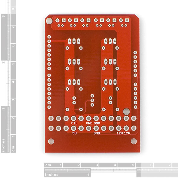
I just assembled this. The holes for the screw terminals are spaced wrong. If you mate the terminal blocks the way they are designed (with the dovetail fittings) then it will not fit on the board. So you just need to assemble as two blocks of 6 terminals - then it fits in the PCB okay.
When driving power MOSFETs the gate acts as a capacitor, is there some current limiting resistor between it and the microcontroler pin on the Arduino board? If not, wont the inrush current damage the driver pin on the chip? Or is it that the inductance of the PCB trace, combined with the small gate capacitance, limits the current to acceptable levels? Sorry if this is a dumb newbie question, I have only dealt with larger, non logic level power MOSFETS.
It's always a balancing act -- if you put two much resistance on the line, your RC constant starts becoming noticeable and the the transistor will be operating outside of the saturation region for a longer period of time (so it will get much hotter) -- especially when it's being used for PWM/high-frequency switching operations.
The inputs on most micros these days have clamping diodes and other protection circuitry which usually mitigates the need for the series resistors. I assume that's why they're absent?
What this thing needs is a "heatsink shield" to go on top. It could be made easily out of a rectangular piece of aluminum using a square punch and a drill.
Something like this:
http://img829.imageshack.us/img829/3718/shieldhq.jpg
You would just have to be careful that the heat sink was electrically isolated from the cases on the MOSFETS. The flange is internally connected to the drain in the transistor.
This week's 'new product video' says it very likely that the PCB traces burn out before the mosfets wil. So for how much are those PCB traces rated? (ballpark if you must) I know y'all like to see sparks flying around for fun. (pun intended) Well, me too, but not inside the house.
The output traces are 0.080", so if you're willing to let the board get warm, they'll carry about 8A. (Google Trace Width Calculator to check for yourself).
Usually SFE designs seem reasonable enough -- however, I'm a little perplexed at the absence of catch Schottky diodes across the source-drain terminals, especially since I'm sure some users will buy this to control motors -- in which case catch diodes are absolutely essential.
Otherwise, it looks like an important addition to the plethora of Arduino shields -- I especially like the ATX power supply input and screw-terminal outputs. I would predict many Arduino users don't have any other high-wattage DC supply other than an ATX PSU -- great design decision.
Unless my eyes deceive me, there are holes and silkscreen on the board for these diodes to be placed should they be required (they are right next to the screw terminals.) It would be nice if a link to an appropriate part were part of the product description, though, for less clicking and more shopping! :-)
Those are .1in header footprints. They're there for those who don't want to use the screw holes.
Unless I'm mistaken these are already incorporated into the mosfet as many mosfets do contain a flyback/protection/catch diode. Take a look at the data sheet. There's one in the symbol and some specs for it on the bottom of page 2.
They do contain an intrinsic diode due to the design of the MOSFET.
However, it's more of an artifact of the design (an NPN MOSFET has to have a PN junction somewhere...) than a flyback/catch diode. It will be slow, high forward voltage, and low reverse voltage, and it's in the hottest location on the PCB (inside the power MOSFET). A Schottky (or fast rectifier) across the source and drain will be far superior to the body diode of the MOSFET.
The flyback diode goes across the inductive load, not the fet, if you are trying to clamp the inductive kick back when the fet turns off.
Ya. A flyback diode across the load terminals (for inductive loads) will need to be added or boom.
Forgive me since I'm extremely new to the Arduino, but wouldn't it make more sense to have the ATX connector on the same side as the usb & power connectors?
The part of the board sticking out would not fit on top of the power jack and usb port.
I'm confused. Does this break out the 3.3v, 5v, 12v, and -12v? Or just the 12v to 6 mosfets?
Schematic says 12 volts. I suppose you could cut traces and wire it to 5 volts though.
I would have thought that the 5 volt standby supply could be used to power the Arduino via a jumper. Revision 2 maybe?
I thought the same thing.
I think there's a trace from one of the 5v pins on the ATX supply to the 5V pin on the arduino
There is one, certainly.
Meaning the Arduino draws power from the ATX connector, not needing an external powersupply in the front? :)
(Sorry if that was obvious. I'l still abit new )
Yeah, the schematic wasn't uploaded when I posted that comment.
Sparkfun should add a solder jumper to allow users to select whether or not they want the Arduino powered by the Atx connector.
96 Watts per channel isn't bad.
(with an appropriate heat sink I imagine.)
That's 8 amps at 12V * 6!