- Home
- Product Categories
- Switch
- Rotary Encoder - Illuminated (Red/Green)

Rotary Encoder - Illuminated (Red/Green)
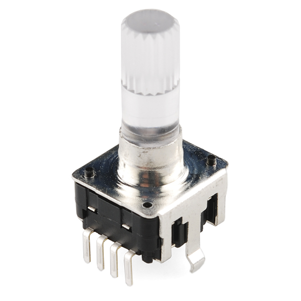
Rotary encoders are used similarly to potentiometers. They're different from potentiometers in that an encoder has full rotation without limits. They output gray code so that you can tell how much and in which direction the encoder has been turned.
This encoder is especially cool because it has a red/green LED built in, as well as a push-button. Look below for the clear knob that goes with this potentiometer.
- Switch Travel: 0.5mm
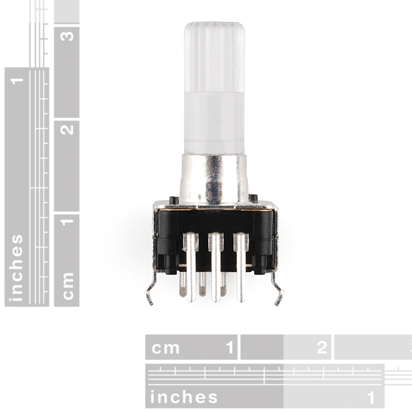
- Shaft Diameter: 6.0mm
- Shaft Length: 18mm
- Vertical Through-Hole Mount
- Red/Green LED
- Pushbutton
Rotary Encoder - Illuminated (Red/Green) Product Help and Resources
Common Cathode
If you look at the dimensional drawing, the LEDs and button are common cathode. If you are using code in the GitHub repository, make sure that you flip the logic on the LEDs to properly light up and use a pull UP resistor on the switch.
Core Skill: Soldering
This skill defines how difficult the soldering is on a particular product. It might be a couple simple solder joints, or require special reflow tools.
Skill Level: Noob - Some basic soldering is required, but it is limited to a just a few pins, basic through-hole soldering, and couple (if any) polarized components. A basic soldering iron is all you should need.
See all skill levels
Core Skill: Electrical Prototyping
If it requires power, you need to know how much, what all the pins do, and how to hook it up. You may need to reference datasheets, schematics, and know the ins and outs of electronics.
Skill Level: Rookie - You may be required to know a bit more about the component, such as orientation, or how to hook it up, in addition to power requirements. You will need to understand polarized components.
See all skill levels
Comments
Looking for answers to technical questions?
We welcome your comments and suggestions below. However, if you are looking for solutions to technical questions please see our Technical Assistance page.
Customer Reviews
No reviews yet.
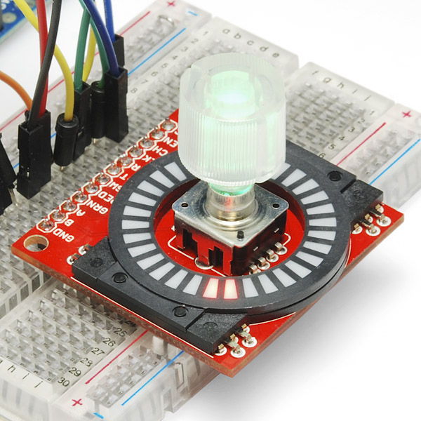
Could someone identify the board shown in the 4th product image — the one with the ring of LEDs(?) surrounding the encoder? I've looked through all the LED/EL products on the site and didn't find anything like this. I would LOVE something that would let me combine a rotary encoder with a visual indicator of the current position; it would be perfect for controlling synthesizers.
Tutorial link invalid, 404 error
The Circuits@Home tutorial is here.
Does anyone know the durability of this encoder? We want to attach it to a motor that will operate at 100 rpm max.
This may be a silly question, but can both red and green be illuminated at once to produce yellow? Or are the colors limited to red or green?
Yes - the leds are independent of each other. You can energize them one at a time or both together. I bought one of these a few years back and just got it out yesterday to wire to an Adafruit Pro Trinket with their USB volume control software. I added a bit of pwm code to run the leds from green to yellow to red as the volume goes up.
One of the most important property of a rotary encoder is how many pulses it sends out for a full 360° rotation. You guys should get in the habit of putting this in the product post (it is 24 for this one).
Hey, relatively new to the platform. Can you tell me if it is 24 pulses for 360 rotation for each of the channels (so we get a total of 48 pulses every rotation), or is 12 per channel (so we get total of 24 pulses every rotation) ?
Datasheet notes "24 pulses / 360° for each phase"
Thanks, hadn't noticed that.
I wish they set this up for RGB LEDs.
Also when is the break out board going to be released?
Never mind... I had skipped the dimensional drawing. Circuit detail is there. While one might RTFM, one must also RTOFM.
QUADRATURE output, same as most rotary encoders. Calling the 2 bits "Gray Code" is like calling a pipe's T-fitting a "manifold".
Agreed. While quadrature is technically a form of Grey Code, Grey Code is so much more. For example, absolute rotary encoders are capable of telling you exactly where they are in their rotation to n bits of accuracy (even through a power cycle!), where n is the number of rings on the encoder.
Quadrature is 2 bit Grey Code (channel A, channel B), but is not set up to give absolute angle, only relative motion. Good thing, too, since 2 bits of resolution would only be able to give you 90 degree increments.
This would be even more awesome if you had the same thing in panel-mount.
+1 for panel mount :)
I'd like to give rstaph a strong second on this. I have a lot more use for panel mount controls than pcb mount. Not only does panel mount provide more layout flexibility, but it isolates the PCB from a lot of physical stress and strain. Besides, I can usually PCB mount a panel mount control, but not the other way around. I hope whoever does the control shopping for SFE will keep panel mounting fans in mind.
I'd like something that would let me mount everything to a PCB, with a light guide/diffuser for the LEDs, that can then be mounted to a panel. Maybe in black or white. Or brushed aluminum.
Do you have an ETA for this part to become available again?
Thank you, Valentin
any idea?
I would like to know as well.
Comments elsewhere seem to suggest these encoders contain mechanical switches ? rather than digital switches ? Is this correct ? do you need to debounce the signals ?
The big advantage to the Gray code output (thanks, Frank Gray!) is that debounce becomes a non-issue. According to the data sheet, you know you're at the detent when A=1. You're between detents when A=0 but you can wait to declare the cange complete until A=1 again. When there's chatter on A, B will be rock-solid telling you the change is clockwise or counter-clockwise. Once you decide you're at the new detent, you need to move a full half detent to get to the previous value. It's a fun mental exercise to run through an application with chatter.
d/l the data sheet. It's Chinglish, but sufficiently clear to answer your questions. Yes, they are mechanical switches. Yes, you need to debounce them. The data sheet says a max of 3 mSec of bounce.
Yes, how about an optical version Sparkfun? Mechanicals ones won't last all that long if used frequently and bounce will increase over time too.
For the lilypad mp3 can i use an RG encoder or do i have to use the RGB encoder?
Does this rotary encoder have noticeable clicks or resistance? I want to use it to measure the speed of an RC car and I’d like to simply connect it to the axis using a rubber band.
There's a significant amount of rotational friction. This would not be a suitable part for your application. I suggest, if there's room in your car's chassis, rig up an optical rotation counter -- glue some sort of small flag to the axle, which will pass through the channel of an optointerrupter such as this one, or paint a shiny spot on the axle and use a reflective sensor like this one. Then you'll have a single pulse per rotation (which at RC car speeds, is more than enough). Measure the period of one pulse (or count pulses for a set amount of time) and multiply by tire circumference to get speed.
Hi I am new to programing and have a question In you code there is this
include ChangeNotification.h
what is this can any one help
I would like advice on modifying code between the RGB rotary encoder and the RG rotary encoder. My code with the RGB creates green/red blinking with the RG rotary encoder. Any suggestions or resources?
I just ran some tests with a scope to get a sense of the jitter. The test rig had a 56K pull-up resistor (roughly what Atmel claims for the internal pull-ups on an Atmega328) to a 5V supply. Here's what I found:
With no debouncing cap, I got a lot of jitter when turning the knob slowly, especially when a line transitioned low-to-high. The amount was inconsistent but often bounced 800uS or longer.
The recommended 0.01uF caps debounced nicely, with a fairly smooth 1 ms rise to 4V even when turning the knob slowly (which is very close to the 0.9 ms you'd expect from the RC time constant). They were also able to keep up with a quick spin of the knob. I used Kemet C320C103K1R5TA caps for this test.
Using a standard 0.1uF decoupling cap led to voltage drops when I turned the knob quickly. The weak pull-up resistor couldn't charge the cap quickly enough to keep up with the pulses.
Edited to add:
I also got pure software debouncing to work last night. Here's how. The firmware I'm writing has a system-wide 1ms clock. When a pin change interrupt fires for one of the encoder's lines, it starts a 4-tick (3-4ms) timer for that pin, but only if the pin's timer isn't already running. (If the pin's timer is already running, it ignores the interrupt.) When the timer expires, the code samples the pin's value. It ignores any cases in which A and B both change or where A and B both have the original value. If only one of the two has changed, it declares a rotation event which is clockwise if old B != new A and otherwise counterclockwise. We'll see how the scheme holds up as the encoder wears.
dragon fly's butter fly's horse fly's rotary encoder?.....................................................nope doesn't fit the pattern
I used one of these following the bildr tutorial on an arduino and it worked fine, but when I tried to use it on an ATtiny, I ran into problems. Turning the knob didn't adjust the value at all, though at least there was no change when I wasn't moving it. I can't for the life of me figure out why. The ATtiny is operating at slightly slower speed (8MHz as opposed to 16MHz) but should be more than enough when all it's doing is checking an encoder. The first thing I suspected was that the Software Serial was causing problems. So I took it out and used an led to represent the turning. Still didn't fix it. I originally had the software serial tx pin as digital pin 2 on the ATtiny (using pins 0,1 for encoder). I thought maybe this was causing problems so I moved it to pin 4. It started to work better but not near as well as when it was on the arduino. It moved very very slowly when I turned the knob; maybe +- four values for a full rotation. The next thing I tried was changing the bildr code since it declared variables every time it went through the ISR (Interrupt Service Routine) loop. I moved the declarations outside the loop but that didn't help anything. The final thing I did was to get rid of the interrupts and just have it check the status of the encoder pins every time it went through the loop. After this it worked perfectly, even when I moved the Software Serial back to pin 2. So I still don't know what the problem was, but I know it works this way. The only real downside for me is that you can't use any kind of delay in the loop because it may miss part of the encoder turn. If anybody can tell me what my problem was or has had similar experiences, please leave me a comment. You can view a more detailed description here: http://thewanderingengineer.com/2013/05/05/rotary-encoder-with-the-attiny85/
After trying several versions of the decoding methods listed in the references in "Documents" above, below listed is what I have found to work best for me. This encoder seems to have a lot of jitter/bounce/noise and apparently doesn't stay where set, as you can get outputs without moving the shaft. The 3ms delay/software debounce seems to clear up most of this, but counts seem to be getting missed as well. I think hardware debounce will be needed to clean this up further.
James
I'm actually surprised you found so much jitter , and I wonder if you just got a bad unit. I've been using this encoder for several months, as I was testing it for a Wixel based application, and I was finding it to be very stable... certainly very rare a transition would happen without even touching it. Couple of things though. First, I realized a big difference is that I am "polling" (sampling) the encoder at a rapid but constant rate rather than interrupting on change as you are. My premise is that regular polling offers some of the protection from excessive processing that a denounce routine would offer. You could do the same thing with an interrupt based on a timer rather than on a state change. I basically calculated the max reasonable number of transitions I could expect within a given time, with someone making a fairly rapid adjustment. As long as I was "polling" at least 2X or 4X faster, I'd be safe from losing ANY counts. (In actual use, usually losing SOME counts from a human operated control is acceptable too). Anyway, it seems to have worked out well. There's no way to make an interrupt on state change intelligent, as the interrupt has to do some time based processing just to see if it was valid. And really, doing any kind of delays or waits within an interrupt is asking for trouble, because a badly jittering contact could start eating all your CPU time. The other thing, as I'm sure you've heard before, is that with the gray code output from these encoders, the worst that could happen with a properly written routine is that the final output (the accumulated count) might be +/- 1 off. But really, +/- 1 counts is considered to be the maximum practical accuracy in any digitally acquired count.
PP: Yes, could just be a flaky unit. I don't have an o-scope to check it out in detail. Works ok for my needs as is. Worth $2.95 plus the BOB. I have a polled version also that works about the same as the interrupt version. Haven't tried hardware debounce yet. I saw timer based code out there as well. With the 32bit 80mhz chipKIT I'm not worried about a few cycles.
James
See it in Action
Is this an absolute encoder?
No, it's incremental.
Fun, but not very breadboard friendly (It's just about possible to use it, but the pins especially on the LED/switch side tend to lose contact unless I'm pushing down all the time)
Will you receive more soon? Or it will be replaced by the new RGB version? I prefer these ones, because the others have detents. What should I do? Should I wait?
hello all, I'm new in this field. Does anyone has any code example for using the LED? I don't understand how they are being implemented in applications.
Can anyone elaborate on how the pins need to be connected to read the encoder and use the LED. The Dimensional Drawing didn't answer any questions for me, and the datasheet is useless.
Check the dimensional drawing again. A, B, and C are for the encoder output, and 1, 2, 3 and 4 is for the switch and LEDs.
Check the example above (or anything you find on the net regarding reading grey code), and connect A, B, and C.
am i wrong or do they come from here http://top-up.so-buy.com/?
they also seem to have an rgb version of the encoders.
their product video seems quite ... strange... but promising http://www.youtube.com/user/topup1992
Yeah, these are the top-up ones.
I hope Sparkfun gets the RGB ones next: EC12PLRGBSDVBF-D
Help! I've RTFM'ed but I can't figure out the pin-out. If we put the three at the top, four at the bottom and starting in the upper left hand corner and go clockwise, what am I looking at?
Thanks!
I can't feel a thing...
...which is fine by me but random "detention" might be annoying in some application where several encoders are used.
It looks like the datasheet does not call for a current limiting resistor for the LED but at the same time I do not see one anywhere in the specs. Has anyone hooked it up to see if it does or does not require the resistor?
All LEDs require a current limiting resistor when not using a current driver, or you risk (however rare) damaging the LED. Page 9 contains the forward voltage and current ratings / test values.
I got one of these and they are pretty nifty. What I would really love is this same encoder with through hole mounting.
Isn't it already through-hole? (per description and product photos). Did you mean surface mount?
I mean through hole mounting, with a threaded section around the shaft. Not through ole soldering.
With this one you need to solder to a board and then mount the board so the shaft goes through any sort of panel.
that's called Panel Mount
Can a pot be replaced with a rotary encoder? Or are rotary encoders used for totally different things than what a pot is used for?
Well, that depends on what you want to use it for. Yes in general, but if you need a analog output a pot would be easier. You could do analog with a encoder but then you would need a digital pot to go with it if you needed a analog output.
Do these encoders have "clicking" in between each step like the COM-09117 or do they have smooth rotation?
There are detents, yes. You can feel very small steps. It's not completely smooth, but it doesn't necessarily click either.
Mine had no detents either. Pretty disappointed.
Either they vary unit to unit or I'm losing my sense of feel!
I bought one and absolutely cannot feel the slightest detent. Not that I mind - I didn't buy it for the detent, just for the cool factor. Got one of the circular bar graphs as well. Now I need to make some sort of cool framistat with them.
Keep the fun new products coming; you will soon own my bank account.
Ditto. The one I received did not have detents.