- Home
- Product Categories
- Arduino Boards
- Mega Pro 3.3V

Mega Pro 3.3V
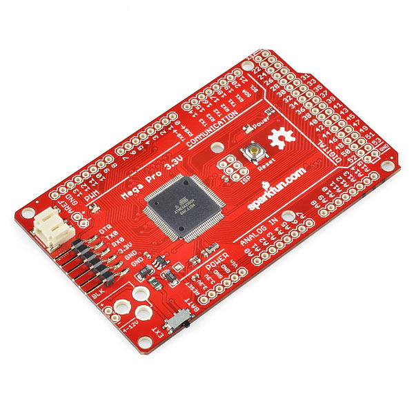
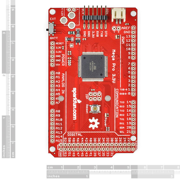
It's powerful, it's portable, it's Pro! We're continuing our Pro series of Arduino-compatible micro-controllers with the addition of the Mega Pro. This is a 3.3V microcontroller running a version of the stk500v2 bootloader at 8MHz. Just like the other Pro-series boards this board is built with all SMD components and comes with no headers populated in order to minimize the cost and the board profile. Of course this board has the same pin-configuration as the Arduino Mega so it is dimensionally shield compatible (but do keep in mind that this is a 3.3V board unlike the Arduino Mega).
The Pro series is meant for users that understand the limitations of system voltage (3.3V), lack of connectors, and USB off board. This board connects directly to the FTDI Basic Breakout board and supports auto-reset and the DC power jack footprint is available, but not populated.
Note: If you are using Arduino, modifications were made to the bootloader to support the 3.3V system, you will need to download and install a new board definition so that the Mega Pro can be programmed in the Arduino environment. The .zip archive below contains all of the files that you'll need including a "readme" file with simple instructions for how to install them. OR you can use Wiring and not worry about this since the board is officially supported. You will need to download the board definition files here.
Not sure which Arduino or Arduino-compatible board is right for you? Check out our Arduino Buying Guide!
- ATmega2560 running at 8MHz external resonator
- Low-voltage board needs no interfacing circuitry to popular 3.3V devices and modules (GPS, Accelerometers, sensors, etc)
- USB connection off board
- 3.3V regulator, 500mA max
- Over current protected
- Reverse polarity protected
- DC input 3.3V up to 12V
- Resettable fuse prevents damage to board in case of short
- Power select switch acts as on/off switch
- Schematic
- Eagle Files
- [Datasheet](http://cdn.sparkfun.com/datasheets/Components/General IC/2549S.pdf) (ATMEGA2560V-8AU)
- Board Definition Files (Wiring 1.0)
- Board Definition Files (Arduino 1.0)
- Board Definition Files (Arduino 0022)
- GitHub (Design Files)
Mega Pro 3.3V Product Help and Resources
Core Skill: Soldering
This skill defines how difficult the soldering is on a particular product. It might be a couple simple solder joints, or require special reflow tools.
Skill Level: Rookie - The number of pins increases, and you will have to determine polarity of components and some of the components might be a bit trickier or close together. You might need solder wick or flux.
See all skill levels
Core Skill: Programming
If a board needs code or communicates somehow, you're going to need to know how to program or interface with it. The programming skill is all about communication and code.
Skill Level: Competent - The toolchain for programming is a bit more complex and will examples may not be explicitly provided for you. You will be required to have a fundamental knowledge of programming and be required to provide your own code. You may need to modify existing libraries or code to work with your specific hardware. Sensor and hardware interfaces will be SPI or I2C.
See all skill levels
Core Skill: Electrical Prototyping
If it requires power, you need to know how much, what all the pins do, and how to hook it up. You may need to reference datasheets, schematics, and know the ins and outs of electronics.
Skill Level: Competent - You will be required to reference a datasheet or schematic to know how to use a component. Your knowledge of a datasheet will only require basic features like power requirements, pinouts, or communications type. Also, you may need a power supply that?s greater than 12V or more than 1A worth of current.
See all skill levels
Comments
Looking for answers to technical questions?
We welcome your comments and suggestions below. However, if you are looking for solutions to technical questions please see our Technical Assistance page.
Customer Reviews
No reviews yet.
For anyone still trying to use this board or a similar ATMega2560 board at 3.3V 8MHz, I was able to get this working with the Arduino IDE 2.3.2. Just copy this "Sparkfun" folder to "%AppData%\Local\Arduino15\packages", restart Arduino IDE and it should show up as Mega Pro 2560V 3.3V.
Folder here: https://drive.google.com/drive/folders/1XYRfQsm4nI1GDbV08nDKGDaMgXhQQScK?usp=sharing
just got this today, trying to program with arduino 022 and a sparkfun FTDI basic, i get this error and the arduino IDE sort of locks up, so that i have to restart the program to attempt to upload again.
avrdude: stk500_2_ReceiveMessage(): timeout
Are you adding the mega 3.3V device to the boards.txt file as indicated in the readme file here?
yeah, added the board and selected it from the list, no sweat. fiddled around with the config file to try different baud rates, but that didn't help. here's a verbose output trying to upload the blink example sketch:
Binary sketch size: 1612 bytes (of a 258048 byte maximum) /Applications/Arduino.app/Contents/Resources/Java/hardware/tools/avr/bin/avrdude -C/Applications/Arduino.app/Contents/Resources/Java/hardware/tools/avr/etc/avrdude.conf -v -v -v -v -patmega2560 -cstk500v2 -P/dev/tty.usbserial-A8004w6D -b57600 -D -Uflash:w:/var/folders/VV/VVhTf+NzEVyix5U1wAH++U+++TI/-Tmp-/build4003381142504225074.tmp/Blink.cpp.hex:i
avrdude: Version 5.4-arduino, compiled on Oct 9 2007 at 11:20:31 Copyright (c) 2000-2005 Brian Dean, http://www.bdmicro.com/
Contact techsupport at sparkfun dot com and they will help you get a working board. Thanks.
Any fix for this issue? I am having the exact same issues with 0023, OSX, and this board.
i contacted technical support, they sent out a new board, it's doing the same thing...
We fixed the board definition files for arduino 1.0 (see above), but linux (ubuntu) and mac still seem to have trouble. We are looking into this issue and will post a fix soon. Sorry for the troubles.
We have found a fix for *nix. If you have an older board and don't have a programmer, please contact techsupport and they will help.
This is the same error I get when trying to download code to the board on my mac too. In addition to trying using my mac I have also tried using a completely separate windows machine and it gives me the same error but with more details as to what its doing: http://pastebin.com/cudy6BKr I hope this helps, I'm really looking forward to using this board :D
Update: I just installed Wiring 1.0 and the Sparkfun board definition files and downloaded through that, no luck with that either, same errors.
I've been having the exact same problem ever since I received it just under a week ago. I am using Arduino IDE 0023 on mac. Although I have tried using windows and it gives me the same error.
i just updated to 0023, on a mac as well, no dice, same error
The one thing that irks me about the Arduino mega (that you also seem to have reproduced) is that a good 16 I/O pins of the 2650 are left unconnected and unusable. OK, adding them might interfere with the shield connections, but they could at least be brought out to solder pads on the board. (There is at least one Arduino mega clone that DOES bring out ALL of the I/O pins). Maybe on the next board spin ... PLEASE!
You definitely have a point. Though if that's bad, I think the upcoming Arduino DUE with it's ARM processor will have almost (if not more than)half the pins not broken out as it has the same pin layout as the Mega. It would be nice if there were little square SMD pads on the bottom of the boards so that we could make backpacks that could breakout these pins so that they could be used. :-|
This observation might be 3 years late, but although the Due (and other ARM boards) are screaming fast and have tons of I/O and memory, they consume about 30x as much current. That's worth knowing if you're intending to build a battery product. I've been comparing the Teensy products with the Mega Pro, and for my intentions it comes down to whether I can afford 30 mA drain on a standalone battery with the Teensy vs the 3-5 mA on a board like this. Add in a Zigbee module to your project, and you have potentially serious battery life issues.
that irked me about the regular arduinos too. though if you need that many I/O's you'd probily benifit from a custom PCB.
Will there be a 5V version coming out?
Yes, it's in the works.
quick i need it :P
me too!! 3.3V doesn't always cut it. :-{
Can the board definition files be updated for the Arduino IDE 1.6? I cannot get this board to work in the new version.
Instructions to get this working with Arduino 1.5.4. May or may not work with higher versions.
Plug in the 3.3v version of the SparkFun FTDI Basic Breakout to the 3.3v Mega Pro board. It can only go in one way.
Download the Board Definition file for Arduino 1.0.
Unzip.
Copy the mega-pro-3.3V directory into the IDE's Java/hardware/arduino directory. NOTE: On OSX, you have to right-click on the Arduino application, select "Show Package Contents", and go to the Contents/Resources directory. There you will find the Java directory, and you can proceed.
Copy the platform.txt and programmers.txt files from Java/hardware/arduino/avr to Java/hardware/arduino/mega-pro-3.3V.
Edit the Java/hardware/arduino/mega-pro-3.3V/boards.txt file as follows:
Add the line
just above the line mega2560v.upload.protocol=stk500v2.
Add the line
just above the line mega2560v.bootloader.low_fuses=0xE2.
Restart the IDE (if you had it open). You should now be able to select Tools > Board > Mega Pro 2560 3.3V. Verify everything works with the Blink program as described under the "Launch and Blink" section here: https://learn.sparkfun.com/tutorials/installing-arduino-ide
Rejoice in the blinking of the light.
The dates below are out of sync.
It may be obvious to everyone else but it was the zip file mega_pro_3.3V_v12.zip that worked for me (in 1.0.6) but the folder actually in the hardware folder needed to be mega_pro_3.3V not the mega_pro_3.3V_v12 folder.
A far as I can tell the hardware install files do not work with the new versions of the Arduino IDE 1.6.x - I had to revert to 1.0.6 to get the 3.3v board to appear and work without error.
Why are the SDA/SCL i2c pins pulled up to 3.3v? And are they available on the board?
To upload to the newly released version, Arduino 1.6, use these settings:
Board: "Mega or Mega 2560" Processor: "ATmega 2560"
How much does one of weight?
Hi, I am developing for this board at this time. I need to implement a Watchdog. Searching the Web I discovered that at some point in time, the original ATMEGA2560 did not take care of the Watchdog timer properly (it would not disable it). No word on a fix for this.
I am wondering if Sparkfun adapted bootloader does take care of the Watchdog timer ?
Thanks
Hey Guys, The fuse settings you have used in your board file are wrong. The resonator is not being used. You have it set to use the internal oscillator. The internal oscillator has ±10% accuracy before calibration. The resonator is ±0.01%. You have them set at:
They should be
the mega pro board is rated up to 12V input. but see what happens when we connect a 7V/220mA load using 16 Ohm / 5W power resistor. youtube
the 5v version has a better description of power handling . i was thinking of replacing the regulator with a higher performance one.
TOREX - XC6220B331MR-G - IC, LDO, 1A, 3.3V, SOT-25
Are the source files for firmware available?
Email us at techsupport@sparkfun.com and we should be able to get you the files for the bootloader, although they should be the standard Mega2560 files just recompiled to run at 8MHz.
I received this board just this week. It was satisfying just looking at it. Can't wait to try it - thanks for the enabling!
Is there BOM available for this part? I'm interested in the resonator this board uses - make and part # Thanks
Here is the part number: CSTCE8M00G55-R0
It's available on Digikey.
I am also having this issue with the bootloader not working. Can anyone confirm that this bootloader is actually working ?? on a 3.3v @ 8Mhz ?
Please contact techsupport at sparkfun dot com and they can help you. FYI, there was a short time period a couple of months ago where some boards went out that didn't work on *nix OS, but this bug is fixed in the current bootloader.
If I just replace the 8Mhz resonator with 16Mhz and use external power supply of 5 Volts. I think I can run this at 16Mhz. Of course we will need to replace the following line in boards.txt as follows.
Old content "mega2560v.build.f_cpu=8000000L" New content "mega2560v.build.f_cpu=16000000L"
Does anybody see any issue with this? Thanks
You will also need to burn a new bootloader onto the mega with a programmer. You can use the ATMega2560 bootloader hex in the arduino repo.
Mmmh, could you provide a link please ? I can't find it. I need to fix my SF board bootloader too...
FYI, this thread is talking about switching this board to 16Mhz, which would use a different bootloader hex file than what is currently on the 8MHz board.
If you are looking for the hex files for the 3.3V 8MHz board, they are found in the firmware links on this product page. (here is the one for Arduino 1.0, look in the bootloader file for the hex).
Also, here is the link to the Arduino repo.
Should the bootloader in the "Bootloader Files" folder be called "WiringBoot_ATmega644_8MHz-57600.hex", shouldn't it be "...ATmega2560..."? Should this be the file included http://code.google.com/p/wiring/downloads/detail?name=WiringBoot_sparkfun-megapro-8MHz.hex as posted in a comment above?
Two months ago a1ronzo said the 5V mega pro was in the works. When will this be available. I need it yesterday.
It is very very close.
Thank you for this! I am also looking forward to the 5v version. I was looking at the .brd file.. is the gnd solder pad next to Digital 13 connected? It doesn't appear to be.
Why cant you guys go just a little further with this. Since this is a Pro version take a few liberties and add 3 pin headers (sig,+,-) for all the pins going down the side so we can connect servos and sensors directly. Or better yet just make a small board that just adds those pins that only plus into 6 or 8 pins. Also why not do some nice stuff like battery charger circuit and 3.3 to 5 switch able like seedstudio did. This would be perfect then.
The board definition files are up, but Could you also put up the bootloader files please ? Thank you!
Thanks for putting up the bootloader source (as of Oct 21).
However, could you put up the bootloader instead as a HEX FILE so that it can be loaded directly onto the board using an ISP ?
All, if you should need it, you may find the bootloader HEX file for the Mega 3.3V here (original code authored by Brett Hagman):
http://code.google.com/p/wiring/downloads/detail?name=WiringBoot_sparkfun-megapro-8MHz.hex
I'm downloading the schematic, but it appears you didn't break out the extra ICP or other port pins. There are more there, not just the ones the arduino team chose. Look at the seeed studio version.
Am I missing something? Why would I want it clocked all the way down to 8Mhz?
The atmega2560 is rated at only 8mhz at 3.3 volts. The 5 volt version will clock at 16mhz. It has always been thus.....
You should make a Mega Ethernet Pro! it would be great, and a Pro Mega running at 5 volts because, all that space and only 8 MHz is ridiculous.
Will there ever be a board combined with an RTC IC?
It would be nice to have a single hardware that can wake up based on time without having to add add-ons.
rather pricey
cheaper than the original arduino mega
Wow, I noticed in the board definitions. It seems to indicate that there will be a Mega Pro Mini Version, Would this be the 5v version. Thats a teaser, cant wait to see the production model.
Yet another board with the reset button somewhere you can't really press if you have a shield.
Most shields have reset buttons included.
Where else are you going to put it?? I agree with you that it is annoying though.
It should have been put where the power selector switch is. Sparkfun even sells the correct right angle momentary switch needed: http://www.sparkfun.com/products/10791