- Home
- Product Categories
- IMU
- SparkFun 6 Degrees of Freedom Breakout - LSM303C

SparkFun 6 Degrees of Freedom Breakout - LSM303C
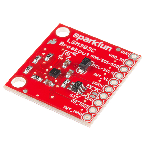
The LSM303C is a 6 Degrees of Freedom (6DOF) inertial measurement unit (IMU) in a single package, specifically developed as an eCompass device. Due to the IC housing a 3-axis accelerometer and a 3-axis magnetometer combined with its low cost, the LSM303C was perfect for us to create this small breakout board just for you! Each LSM303C Breakout has been designed to be super-flexible and can be configured specifically for many applications. The LSM303C Breakout can be configured to generate an interrupt signal for free-fall, motion detection and magnetic field detection!
The range of each sensor on the LSM303C is configurable: the accelerometer's scale can be set to ±2g, ±4g, ±6g, or ±8g, while the magnetometer has full-scale range of ±16 gauss, and supports I2C and SPI communication.
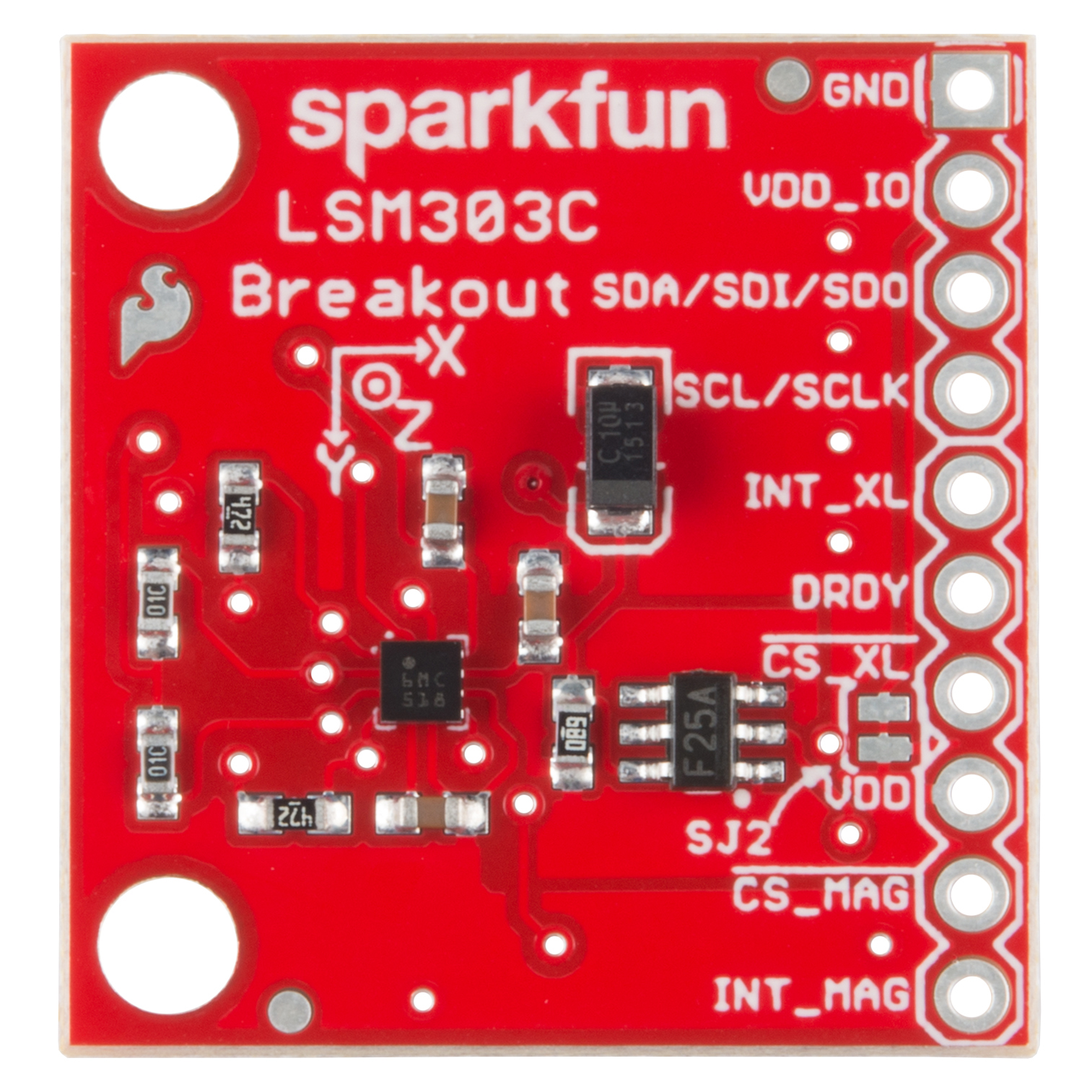
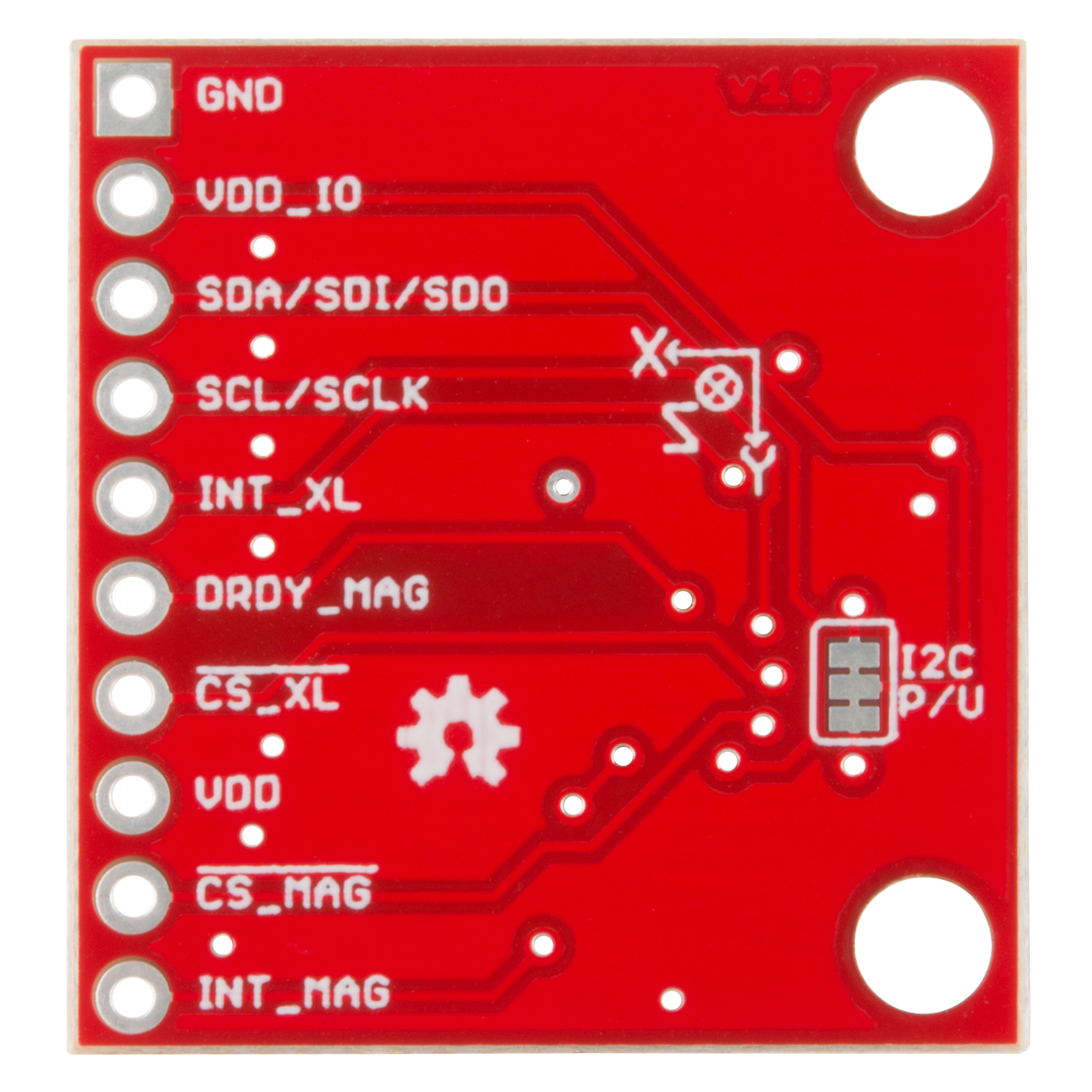
Each pin has been broken out on the LSM303C, with 10 plated through-hole connections featuring power and I2C and SPI functionality, interrupt outputs, and accelerometer and magnetometer data out. Please keep in mind that the LSM303C is a 2.5V device so supplying voltages greater than ~4.8V can permanently damage the IC. As long as your Arduino has a 3.3V supply output, you shouldn't need any extra level shifting.
- 3 magnetic field channels and 3 acceleration channels
- ±16 gauss magnetic full scale
- ±2/±4/±8 g selectable acceleration full scale
- 16-bit data output
- SPI / I2C serial interfaces
- Analog supply voltage 1.9 V to 3.6 V
- Power-down mode / low-power mode
- Programmable interrupt generators for freefall, motion detection and magnetic field detection
- Embedded temperature sensor
- Embedded FIFO
- Schematic
- Eagle Files
- Hookup Guide
- Datasheet (LSM303C)
- GitHub (Design Files)
- GitHub (Library)
- Product Video
SparkFun 6 Degrees of Freedom Breakout - LSM303C Product Help and Resources
LSM303C 6DoF Hookup Guide
October 8, 2015
A basic guide to get started with the LSM303C 6 Degrees of Freedom Breakout.
Core Skill: Soldering
This skill defines how difficult the soldering is on a particular product. It might be a couple simple solder joints, or require special reflow tools.
Skill Level: Noob - Some basic soldering is required, but it is limited to a just a few pins, basic through-hole soldering, and couple (if any) polarized components. A basic soldering iron is all you should need.
See all skill levels
Core Skill: Programming
If a board needs code or communicates somehow, you're going to need to know how to program or interface with it. The programming skill is all about communication and code.
Skill Level: Competent - The toolchain for programming is a bit more complex and will examples may not be explicitly provided for you. You will be required to have a fundamental knowledge of programming and be required to provide your own code. You may need to modify existing libraries or code to work with your specific hardware. Sensor and hardware interfaces will be SPI or I2C.
See all skill levels
Core Skill: Electrical Prototyping
If it requires power, you need to know how much, what all the pins do, and how to hook it up. You may need to reference datasheets, schematics, and know the ins and outs of electronics.
Skill Level: Rookie - You may be required to know a bit more about the component, such as orientation, or how to hook it up, in addition to power requirements. You will need to understand polarized components.
See all skill levels
Comments
Looking for answers to technical questions?
We welcome your comments and suggestions below. However, if you are looking for solutions to technical questions please see our Technical Assistance page.
Customer Reviews
No reviews yet.
This is not the same as the LSM303. The simple heading example does not work on the LSM303C. As for a simple compass example one does not exist... Just a heads up all...
Posting in case anyone else had similar difficulties getting this to work. I tried testing this board with a 5V, 16Mhz Arduino Pro Mini using the Sparkfun LogicLevel breakout board to convert the 5V signals to 3.3V. Other than the addition of this logic level converter I followed the provided Hookup Guide Tutorial but kept getting the "Failed setup" error. Turning on the Debug flag in the library, it became clear there was an issue with the I2C communication. After a bit of research, I started questioning whether or not there might be an issue with the pullup resistors on the A4, A5 pins. If you look on the backside of the Arduino Pro Mini there are two sets of pads for which I'm assuming you could add "external" pullup resistors. I hadn't added these since, I assumed the the Sparkfun LSM303C library was making use of the internal pullups. This might not be the case, and/or the use of the logic level converter may be interfering with the use of these pullups in some way? In either case, just adding the code "Wire.begin();" to my setup loop (which activates the internal pullups) resolved the issue. Hope that helps anyone having similar issues!!
Nice. Does your code have this line:
if (myIMU.begin() != IMU_SUCCESS)? The begin method in the LSM303C class makes calls toWire.begin();andWire.setClock(400000L);. I'd be curious to know if I've got something missing.Why is this product listed under the Gyros tab when it doesn't contain a gyroscope?
Great question. I'll make sure someone is aware of this.
Anyone successfully use this lsm303C ?How to get headings?
I noticed the power supply sequencer between VDD_IO and VDD. I imagine that this was added after some pain. Do you care to talk about it? What is the function of that circuit. Does the chip misbehave if the power supply is sequenced incorrectly?
Why do you include interrupts on the boards and in the product description but not in the libraries, tutorials or example sketches? Is there an issue with interrupts on Arduino for 3.3V devices using Wire? Is there anyone who has taken advantage of these capabilities on the Arduino?
Often the example sketches, tutorials and even libraries are meant as a place to get you started with the basics which usually means reading the data. Anything more really we leave up to the user to figure out (datasheet and schematic should be all you need) as there tend to be an infinite number of more advanced cases/uses.
Is it possible to connect this breakout board to an arduino UNO (5V) using two 330 Ohm resistances, as for the MMA8452Q Accelerometer Breakout board ? See section "Simple Hookup" of https://learn.sparkfun.com/tutorials/mma8452q-accelerometer-breakout-hookup-guide?_ga=1.100424669.2117008986.1449248271. Thank you in advance for your reply.
Has anyone had difficulty with using the associated libraries for this product? I am currently trying to run the example codes provided in the library, however, when I check the serial monitor I am not receiving any readings (baud is set correctly - when I set debugging statements to '1' I get a "reading from register: 0x1E" message).
I'm unable to find that string in the code, so I'm not sure where that's coming from. Are you sure that's a direct quote? If enabling debug messages prints messages, then the serial monitor is working. I'd recommend contacting tech support with a little more information. Which example sketch are you running? Which Arduino are you running? Is that a 3.3V Arduino, or are you level shifting the IO? The MinimalistExample should print
Failed setupif the IMU wasn't communicating with the µController.