- Home
- Product Categories
- Cellular
- GM862 Evaluation Board - USB

GM862 Evaluation Board - USB
Replacement: None. The GM862 has been retired so we're no longer building the evaluation board. This page is for reference only.
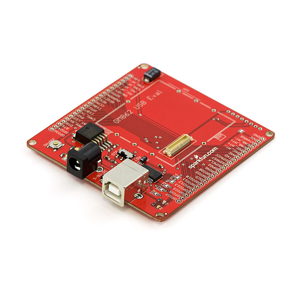
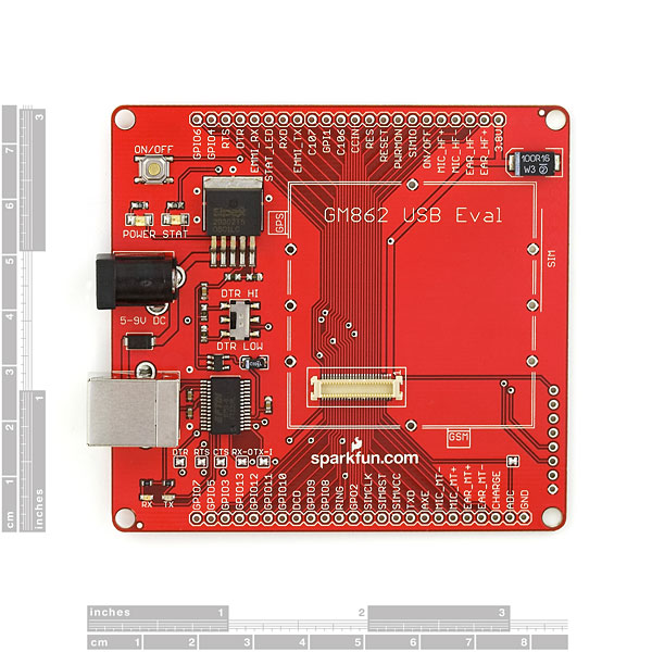
The next generation evaluation board for the GM862. The GM862 Eval USB has a full 50-pin breakout, USB B connector, and a Python script enable switch. This allows connections to the audio, digital, and camera interfaces on the GM862 module. The GM862 Eval USB attaches to any USB port and appears as a standard com port. Power up the board, turn on the module, and you can start sending and receiving AT commands via HyperTerminal. No messy 3.8V regulation. No tricky 3.3V to RS232 level converter. It's all done for you!
Communication and power via USB. The USB chip can be disconnected to allow for external control of the TX and RX pins on the GM862 module (3V logic only!).
The board comes fully assembled with 50 pin Molex connector part # : 53748-0504, 3.8V power regulation circuitry, and supporting circuitry. The Molex connector is brought out to 5 dual row, .1" headers. 3.8V is regulated through a surface mount SPX29302 LDO regulator.
Note: Some USB ports cannot source enough current to power the GM862 module. If the power supply is inadequate, the module may shut down while attempting to connect to the cellular network. An external power supply will correct this problem if it is experienced.
Drivers:FTDI USB Drivers
**Software: ** TakePhoto example software (Visual Basic source)
Don't forget to set the module to use the North American frequencies: AT#BND=1
Comments
Looking for answers to technical questions?
We welcome your comments and suggestions below. However, if you are looking for solutions to technical questions please see our Technical Assistance page.
Customer Reviews
No reviews yet.
You need good power supply to work with this board. Because after you send your sim card's PIN code, it becomes a bit hungry. Otherwise it shuts down after you send PIN code. I think everything is normal after network registration. USB Interface is a good choice if you have a notebook. Thanks to SparkFun...
If you're trying to connect this board to an Aruino board, you may find this post useful:
http://note19.com/2008/12/20/how-to-control-gm862-from-arduino/
Yeah useful if you want to destroy your module. The module has to be powered by 3.8V and the IO should be 2.8V and you're just running 5V on it straight!. You mad ;).
Where is the camera for this?
Why is the GM862 not being sold anymore?
I bought this lovely board, the gm862 module, an arduino and an external power supply for the usb eval board with a barrel(9V).
Everything works fine when I connect usb cable - eval usb board - gm862 and run Teraterm executing AT commands.
When I try connect eval usb board-gm862 and arduino I face some problems related with the Rx. I can't get no response from the module although at commands run successfully. I read this very helpful post here -> http://tinkerlog.com/2009/05/15/interfacing-arduino-with-a-telit-gm862/ but with no luck. I use external power supply for the gm862 eval board, I leave its USB port untouched, I connect the TXD to TX, RXD to RX and GND to GND respectively to arduino side with no pull up resistors. I power up the device from the onboard button of the eval usb board. I can sent AT commands successfully but I don't receive anything on arduino's serial port when I listen..
I tested the module as I said first with usb cable with Teraterm (no arduino connections) and works absolutely fine. gprs, email, calls, sms. I need to find a solution please.
Thanks in advance.
Tx is transmit
Rx is receive
You have to connect Tx(breakout board) to Rx(micro-controller) and Rx(breakout board) to Tx(micro-controller)
It doesn't help that Spark fun list things the wrong way on their boards....C'mon Spark.
could i reprogram this device (http://www.sparkfun.com/products/10216) using this product
I have used this module in UK and now in USA. It seems very hit and miss on GPRS when the signal strength is 17 or lower. My iPhone and iPad have no problem communicating in the same signal strength. I'm wondering if the spiky curent draw of the modem has an effect on communication reliability.
Perhaps a capacitor on the power supply lines would help?
G
I just made my own breakout using a less heavy power supply and a 1F supercap. It draws 3A only small bursts.
kinda pricy!
I can't get the calculations right for the voltage regulator no matter what numbers I put in. In the datasheet for the LT1528 it says that the voltage can be calculated using:
Vout=3,3(1+R2/R1)+(Isense)(R2)
When I calculate using the values in the schematic, I get:
Vout=3,3(1+(22000/10000))+(0,00013)*(22000)=13,42V
Can anyone help me out on this calculation?
Nevermind.. Found out that the often talked linked to product LT1528 is not the one used in these evaluation boards - for anyone else confused it is the SPX29302 regulator as written in the description (doh).
I'm having an issue with this board.
I bought the MMCX to SMA antenna adapters, and it doesn't fit on this board. It fits in the module fine, but there is a chip on the eval board that is too close to the GPS slot, and the adapter hits it. I'm going to have to file down the corner on the adapter.
That chip really needs to be moved away a couple centimeters.
I had one question about this board. In this board while connecting the USB FTDI chip to the gsm module , do you guys use any level translation in between the 3.3 V signal from the usb and the 2.8 V CMOS on the GM862 side. When I looked into the schematics , it doesn't seem so. So does it mean that the 2.8V CMOS is compatible with the 3.3 V from the USB ?
I read your post and thought you were right, but when I saw that this board has a 2.8V branch I knew that it was for the cmos levels.
If you look at the datasheet for the USB FTDI chip you'll see that pin VCCIO sets what logic level the chip uses. In this case 2.8 V is supplied to VCCIO by regulator U3.
From the datasheet:
5V / 3.3V / 2.8V / 1.8V Logic Interface - The FT232R provides true CMOS Drive Outputs and TTL level Inputs.