- Home
- Product Categories
- GPS
- 14 Channel 10Hz GPS Receiver - Venus634FLPx

14 Channel 10Hz GPS Receiver - Venus634FLPx
Replacement:GPS-10919. The Venus634LPx is no longer being made, however we now carry the Venus638FLPx-L which has improved performance. This page is for reference only.
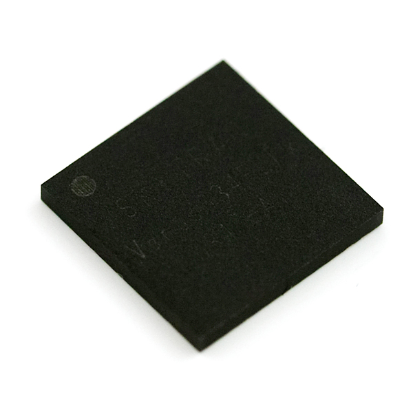
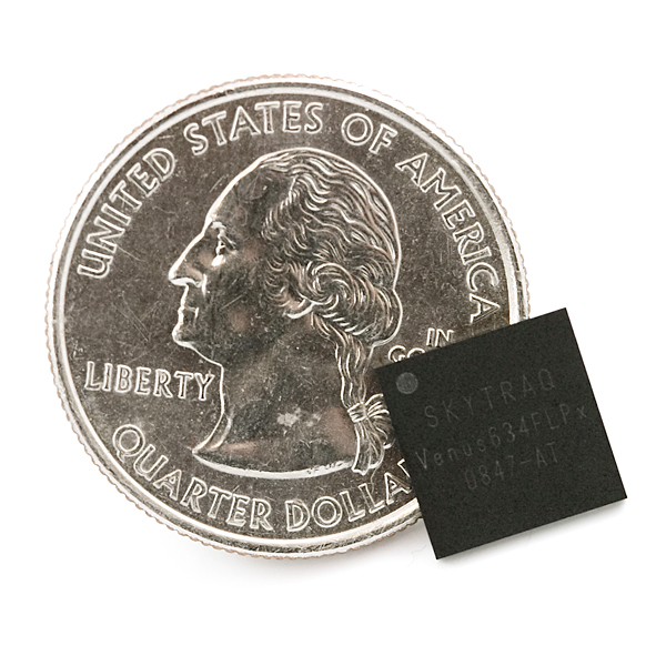
This is the smallest, most powerful, and most versatile GPS receiver we carry. Comes in at a miniscule 10x10x1.1mm package with an amazingly powerful 10Hz update rate, with 14 channel tracking! With two serial ports (UART and SPI interfaces), 28mA operating current, and high sensitivity, this receiver seriously opens new doors for tracking. Module outputs the standard NMEA-0183 or SkyTraq Binary sentences at a default rate of 9600bps (adjustable to 115200bps). Please note this unit requires an antenna matched to 50Ohms. This is even smaller than the GR-10 and MN5010!
The Venus634LPx has improved sensitivity, an integrated LNA (with multipath detection and suppression), built-in RTC, and integrated single power supply making it very simple to use. In addition, the module supports data logging with an external SPI Flash!
Not sure which GPS module is right for you? Check out our GPS buying guide!
Note: According to the manufacturer's specifications, the IC requires a 24 hour pre-bake at 125C before SMD mounting in order to prevent issues with moisture .
- 51 channel acquisition and 14 channel tracking
- SkyTraq based chipset
- 10Hz max update rate (1Hz default)
- Integrated LNA
- Single 2.7-3.3V supply
- Power: 28mA tracking
- Sensitivity: -161dBm
- Accuracy: <2.5m
- Hot start: 1 Seconds
- Cold Start: 29 Seconds
- Supports active or passive antennas
- Supports SBAS (WAAS, EGNOS, MSAS)
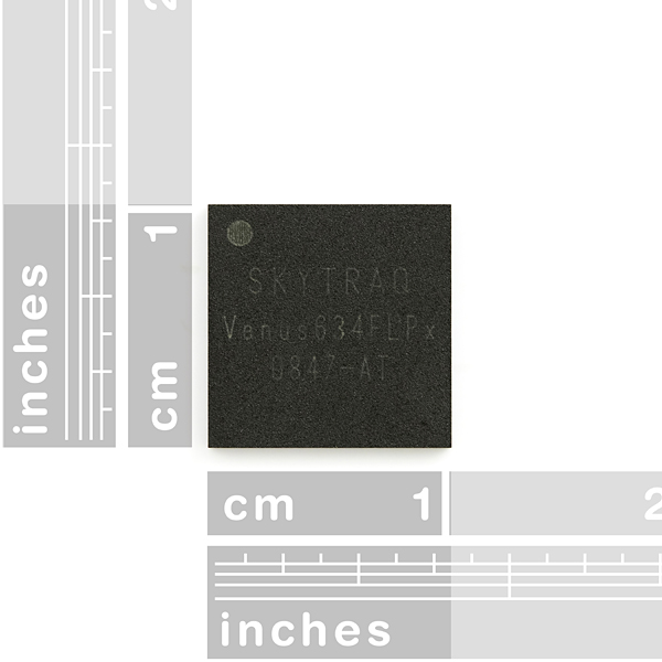
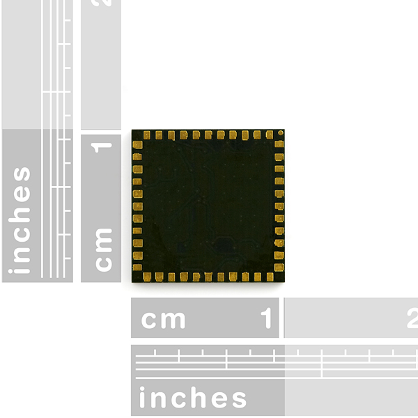
- 10 x 10 x 1.1mm, LGA44 package
- Venus634FLPx Dataheet
- Binary Command Set
- [GPS Viewer Software](http://www.sparkfun.com/datasheets/GPS/GPS Viewer_1124.zip)
- Datalogging Datasheet
- Design Guidelines
- Reference Layout
- Layout Guidelines
- Handling Guidelines
- Firmware Update
Comments
Looking for answers to technical questions?
We welcome your comments and suggestions below. However, if you are looking for solutions to technical questions please see our Technical Assistance page.
Customer Reviews
No reviews yet.
I'm confused. I see the firmware update file above, but nowhere in the documentation can I find how one is supposed to go about feeding this firmware upgrade to the chip.
Any thoughts?
I am having good results using the GPS-00178 antenna with this receiver, but what really stands out for me is the communication I have had with the manufacturer, SkyTraq. I typically receive a response to emails within a couple of hours, and they have been very helpful in resolving some issues I've had with the unit. In particular, they updated their firmware to include full PVT data as binary output after I mentioned that it was critical for my application. SkyTraq gets an A+ from me for customer service.
Just Wondering, is there a part in the Sparkfun library in eagle for this... I really want to integrate it into my design!
The pictures with rulers are not correct. The chip is 10mm square. The last time I checked, 10mm was still equal to 1cm and not a fraction thereof.
You're correct. Thanks for the catch. Fixed!
Yep - our fault. Fixed now.
Seriously? You retired a part that I just made a board for?! :-( NOT NICE OF YOU SFE! :O :P
This only needs pre-bake: (quote from the datasheet)
"if it has been removed from the protective seal for more than 48hours."
Cheers
These seem to be a huge PITA to solder (even with a stencil, they are not kidding about the prebake). However, support from the manufacturer is second to none, so I've been toughing it out.
http://cid-478828d520112340.office.live.com/self.aspx/.Public/STI%5E_01.04.48-01.10.29%5E_npse%5E_VENUS634.zip
Here's the latest firmware for the VENUS 634
Would you have a breakout board avaible for the Venus634FLPx GPS?
The output latency is exactly the problem the basic gps have.
This is because the output is filtered in order to get a position/speed which doesn't move too much. But for some users (and I believe you belong to them), getting very "fresh" data is important (AHRS with GPS for example), and I thought this GPS would solve the problem with its 10Hz update rate...you actually confirmed that it is not the case.
The 10Hz seem to be in fact extrapolated, as usual.
I have tested a lot of GPS modules, and the winner is:
- Ublox : http://www.sparkfun.com/commerce/product_info.php?products_id=8889
This is a true 4Hz GPS (without latency when properly set) as you can choose "pedestrian", "car", "airborne 2g", airborne 4g"...the output is of course noisy.
It is the one I use in my UAV.
Antoine
Has anyone else noticed severe latency or maybe just averaging of the speed reading from this chip? I have the position rate turned up to 10Hz but during acceleration and deceleration the speed seems to be about 1-2 seconds behind the true ground speed. The reading are correct once the speed levels off for a few seconds but if I quickly accel and then decel the speed readings never reach the true vehicle speed before braking. I am getting the speed from the RMC message.
Yes, It have tested and speed seems to be filtered or something. This is a big big problem for me. I manufacture GPS racing car data adquisitions. So I tested this module @ 260Km/h accelerating and desaccelerating. Is there any way to solve this problem???
You need to set navigation mode [0x03] to car. If the navigation mode is pedestrian the receiver filters movement to reduce wander.
How do I send the gps unit a command from hyperterminal? I currently have the unit connected at 9600 8-N-1 and I can read the NMEA output messages. Is there a key command in order to allow a message to be sent to the gps unit?
Has anyone actually interfaced with this thing using SPI? I see specific references to using it with serial FLASH devices, but I seem to be missing documentation regarding using the interface for processor access to position data.
Thanks,
T
The picosecond this thing has a breakout board I am getting two! But if I order two now there will be a breakout board tomorrow :)
Hi,
Are you guys working on a breakout board with backup battery and antenna ?
Antoine
Hello! Any update on Eagle component and footprint for this GPS? I am in the middle of my PCB and can't go any further :(
General question. What does volume pricing on chipsets like these costs for something like 10k units directly from Skytraq?
I've just always wondered.
That depends on how much the manufacturer likes you and how much business you give them :)
For 1k to 10k quantities of the Flash based part (634FLPx) I'd say your looking at right around $10 each. The ROM based part (634LPx) should be a buck or two cheaper.
Why not hear it directly from the horse's mouth. All you have to do is ask:
info@skytraq.com.tw
Just noticed an error in the description of the 634FPLx.
"In addition, the module supports data logging with an internal SPI Flash! "
The direct to flash logging capability is built-in, but the SPI Flash is an external part, NOT internal.
about page 2 in the datasheet:
Operational Limits
Altitude < 18,000m or
Velocity < 515m/s
COCOM limit, either may be exceeded but not both
does this mean we can use this for ultra hight altitude balloon flights ?
what happens when one parameter is exceeded ?
and at both ? and how will it recover again ?
You wrote that it needs a 50 Ohm antenna, does that mean that it works with the 'Antenna GPS Chip-Scale' listed here: http://www.sparkfun.com/commerce/product_info.php?products_id=8418
I've just tested the Venus634FLPx with SparkFun's GPS-09131 chip antenna, and was unable to get a fix even on a wide open hilltop. The two are connected with a 50 ohm coplanar waveguide, which I think is a bit overkill for the 3 mm gap separating them.
I thought I might be able to make this one work if I was really careful about the design, but at this point I wouldn't recommend trying it unless you have a substantial RF background and proper test equipment.
We are still trying to figure that out. The chip antenna should work, but it is very finicky. We'll get sure to post if we get the chip antenna to work with this IC.
When you test it, create some "as used" scenarios. E.g. put it in small plastic enclosure with other active micro-controller circuitry to test for antenna detuning due to near field effect and the type of dialectic of the enclosure.
You will be better off with a standard ceramic antenna. These tiny antennas tend to de-tune very easily depending upon their environment. Layout must be exactly to manufactures guidelines.
I've have played with this GPS receiver and it is very good. I'm glad to see Sparky building a board, I was going to. Sparky, keep it simple: Serial I/O, optional logging EEPROM, and rechargeable battery back up, no on-board regulator, ceramic antenna 18x18mm [OK], or 25x25mm[better] with circuitry on one side and antenna on reverse. Place the .1 connectors along two opposite edges of the PWB so that they can be used to secure and hold firmly the receiver board on the host PWB.