- Home
- Product Categories
- Components
- Relay Control PCB

Relay Control PCB
Replacement:COM-11041. The new board is routed to provide more isolation for the high voltage traces. This page is for reference only.
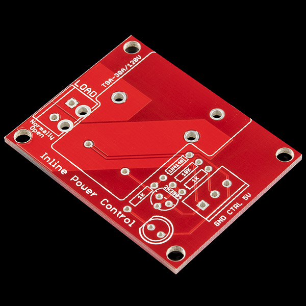
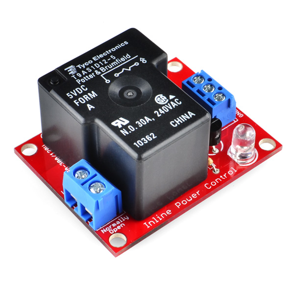
Based on the Controllable Power Outlet Tutorial, this is the bare PCB that allow you to switch high voltages with a simple 0 to 5V GPIO on any microcontroller.
Note: This is only the bare PCB. You must buy the through-hole components and solder them to the PCB.
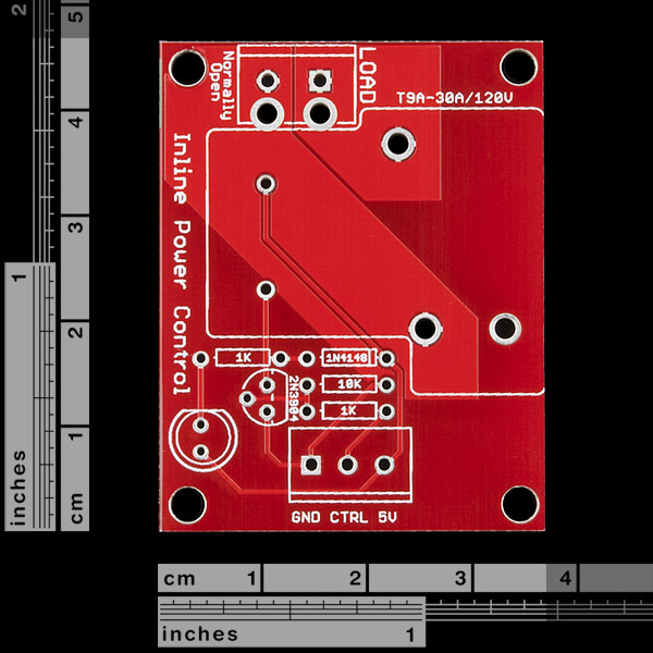
BOM **(bill of materials can also be found in the related items below):**
- 1 Relay (COM-00101)
- 2 1K Resistor (COM-08980)
- 1 10K Resistor (COM-08374)
- 1 Diode (COM-08588)
- 1 Transistor (COM-00521)
- 1 LED (COM-00528)
- 1 2-pin Screw Terminal (PRT-08432)
- 1 3-pin Screw Terminal (PRT-08235)
- Schematic
-
This PCB and parts are really meant for someone with mild experience. If you're uncomfortable soldering or dealing with high voltage, please checkout the PowerSwitch Tail. The PowerSwitch Tail is fully enclosed making it a lot safer.
Comments
Looking for answers to technical questions?
We welcome your comments and suggestions below. However, if you are looking for solutions to technical questions please see our Technical Assistance page.
Customer Reviews
No reviews yet.
Why doesn't somebody just make a part that contains a relay, transistor, diode, etc? Then there wouldn't be any required external components.
Yes! I've been looking for a relay-board just like this. So that I'm able to solder a NPN transistor to the board, and control the relay by 3.3V. This looks like a great product, i can't wait until it arrives in my mailbox! :D
PhysComp Hobbyist: Can any electrical engineer out there tell me if these load traces will actually handle 240v @ 15-30Amps like the relay that mounts to it?
Unlikely. The 10A traces my roommate are using on our new LED sign/deathray are .25" wide, but we are going for a huge factor of safety. According the trace width calculator that Advanced Circuits (the board house we frequent), a 283 mil (.283") trace will take 10A assuming a 1 oz/sqft copper layer and 10 degrees C temp rise.
Calculator is located here: http://www.4pcb.com/index.php?load=content&page_id=95
While researching this part, I read this comment and started to get a little discouraged. I'm looking at using some of these to control a blower motor in a car. Basically, just removing the mechanical switch and replacing with a uControlled relay setup (complete with uber cool illuminated push buttons!).
But, an idea popped into my head: remove the traces and just solder to the relay's contacts. In my uneducated mind, this would work. I've been out of electronics "hacking" since high school (10+ years), and have recently started working the muscles again.
So, can anyone shed some light on this? Would removing the traces allow you to use the full capacity of the relay? Or are there some other pitfalls I'm not thinking about? I was thinking about hot glueing the relay to the board to keep it in place...
Just looked at the pictures again. Guess I decided to overlook the fact that the traces are under layers. :( But, guess you can still just hook up to the contacts and not use the traced leads... It'll look better than just globbing it all in a line.
No, you would be better (and safer) getting a more suitable relay. There is a relay in this family that has spade lugs on the top which you could use (not sure if the same footprint), but if switching high current use good quality lugs (no thin Chinese junk)and use a proper (semi) professional crimping tool, not one of the $5 ones that are no better than pliers.
Beautiful. Thank you SO much. Is 10A the safe maximum or should I fuse all of it at something like 8A? I will be running 24 (yes, you read correctly) of these at a time with a modified ATX power supply (and a couple fans) and will need a fuse so I don't blow anything up, obviously.
I wouldn't count on it, since the traces on this board are only about 1/8 inch wide. Going by Jeff's same parameters (1 oz./sq.ft. Cu, 10 degree C rise), the maximum current through these traces would be about 5.5 amps. Pushing 10 amps through them would likely raise the temps by about 40 degrees C.
I bought one in October last year, when these comments didn't exist and I wasn't wise enough to ask or search - I just assumed the board matched the relay. I ran about 12 amps through it @ 110 VAC. It does get incredibly hot - barely touchable through a plastic enclosure, similar to some older laptop power supplies. Eventually, one of the high-voltage PCB tracks kinda literally blew up (after approximately half an hour daily usage for six months)
Here's another vote for lengthening the board to provide more spacing for the relay on both sides. I have some larger SPDT relays (T9AS5D22-5) that fit into the holes, but they block the components on either side.
Maybe you could also look into stocking that particular relay. It's SPDT, which is handy if you need a N/C pin, and it has top-mounted spade terminals for those of us who are squeamish about running high-voltage, high-current AC through PCB traces.
No need for lengthening... the T9AS5D12-5 is the same package and should fit if you need SPDT... just solder a wire on (the hole is there). However it would be great if sparkfun modified the board to be SPDT... Please?
Mouser P/N: http://www.mouser.com/ProductDetail/TE-Connectivity/T9AS5D12-5/?qs=eFj8uuUn%252bgr6KeQFuhJASA%3d%3d
You may be able to accomplish this by soldering the resistors, diode and 2-pin screw terminal from the bottom of the board. Judging by the footprint of an T9AS1D22-5 (not exactly the one you have, but similar), this should allow you to use the board fine.
Also: SPDT relays allow for two way switch (http://en.wikipedia.org/wiki/Multiway_switching). I wanted to make use one of these in a clapper: then you could clap OR flip the light switch to toggle the lights, whichever you wanted. But I can't, provided I use this board.
Vote for this comment so that SFE will see it!!!
I ordered a few of these and they work great EXCEPT the relay footprint vias needs to be moved 1mm to the right and 1mm up to line up with the silkscreen and not crowd the 2-pin load terminals. With the relay mounted the 2-pin screw terminals cannot mount flush to the board, luckily I am soldering in wire instead.
Sparkfun, can you fix the footprint or move it on the PCB a tiny bit?
The 3-pin screw terminal referenced in the Bill of Materials is incorrect (PRT-08433). It does not fit this PCB, and the holes (and silkscreen) are for a smaller pitch than 5mm.
The 2pin screw terminal does correctly fit the board.
You can disregard this comment as they have fixed the BOM and it now references the correct part. (Unfortunately I was an early adopter who ordered before this was corrected.)
The board works great, though!!!
Might want to change the BOM reflect the change of relay...
When will these be back in stock? I am confused as to why they became o.o.s in the first place as you produce them in house...
We don't product PCBs in house actually. They are on order, but got held up. I'll check into it.
Of course you guys don't actually produce the PCBs themselves... I was thinking more on the lines of assembly. But is your fab house behind schedule?
This product is JUST the PCB. Our stock outage was premature and it's taking slightly longer than usual to get them back in stock. So, one or both of us is behind schedule :-)
Funny, I just hand built one identical to this just a couple of months ago. It was a Diesel Turbo Timer project for my dads diesel truck to cool off the turbo before the engine shuts down. This would have saved me two days of board prototyping.
@sparkfun:
the eagle files on this page are updated?
will be great if you update the pictures, trace thickness and max current information.
Just got the board in today, and it looks like sparkfun beefed up the traces considerably (in addition to changing to a red colored pcb :). I haven't put a load on it yet, but they are probably at least 1/2 and inch wide now.
When do you think that these will be back in stock i am dieing to buy a couple for a project!!! =)
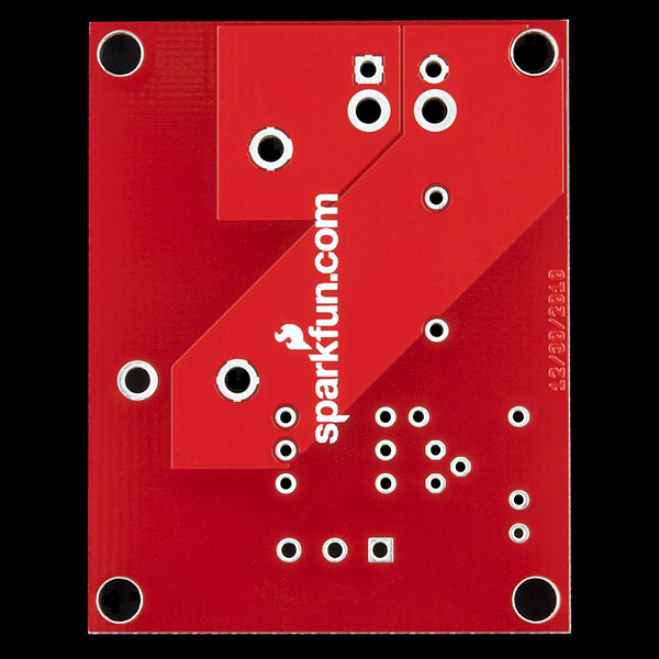
The traces are on the back from the looks of it, so you ought to be able to beef them up by removing the solder mask and soldering down some solder wick.
Love the design. Thanks for the schem. I need more amperage than 5.5 though.
To make sure I run the right software on the right Arduino hardware configuration, I have wired the relay to different digital I/O pins on the different prototype shields that I am using.
In setup() I set the relay CTRL digital pin to input and sense whether it is HIGH or LOW. Relay CTRL appears LOW (value of 0) when attached to a relay board and HIGH (value of 1) when not connected to anything.
If the relay is detected, I change the digital pin to output, exit out of setup(), and continue into loop().
My 3.3V micro could not switch this relay as-is. I bypassed R2 (short) and got it working. The better solution might be to increase R1 to 100K (I had no 100K's on hand).
Also, if 14 gauge solid conductor barely fits into the 2pin screw terminals (an not very securely). I threw them out and soldered directly to the board.
I have 100k on hand, If I just swap R1 with 100k(instead 10k) will it work from 3.3v?
Can any electrical engineer out there tell me if these load traces will actually handle 240v @ 15-30Amps like the relay that mounts to it?
No! Absolutely not. DO NOT USE THIS BOARD FOR HIGH VOLTAGE AT ALL. I hadn't realised this board was released some time ago, I only found out about it when it was recently (Dec 2011) made as a complete kit and I have informed SF that it is very dangerous and should be pulled from sale, which they have since done. Really it should be recalled across the board, as the low voltage traces are dangerously close to the high voltage side. Even more dangerous is the mounting screw hole that is sitting in the middle of the high-voltage trace, with almost no clearance around it. Very likely that if you put a metal screw in the hole, the head would contact the live trace (the silk screen offers little protection from a screw head) and potentially make the chassis live!
Also 30A at 240V is way too high for this little relay. At that sort of current, chances are you're trying to drive a motor and if so that's an inductive load (reactive load) and the relays ratings for reactive loads are much lower - same with any switching device. If you want to switch that sort of current, get yourself a suitably rated contactor, though if you you aren't qualified, I'd suggest not doing it all, as it's likely not safe and probably illegal.
You legends! Ive been after exactly this for some time now.
Could I suggest that you link this page from
http://www.sparkfun.com/commerce/tutorial_info.php?tutorials_id=119
Thanks! :)