- Home
- HTC ExtUSB 11 Pin USB Connector with Breakout

HTC ExtUSB 11 Pin USB Connector with Breakout
Replacement: None. We are no longer carrying this connector in our catalog. This page is for reference only.
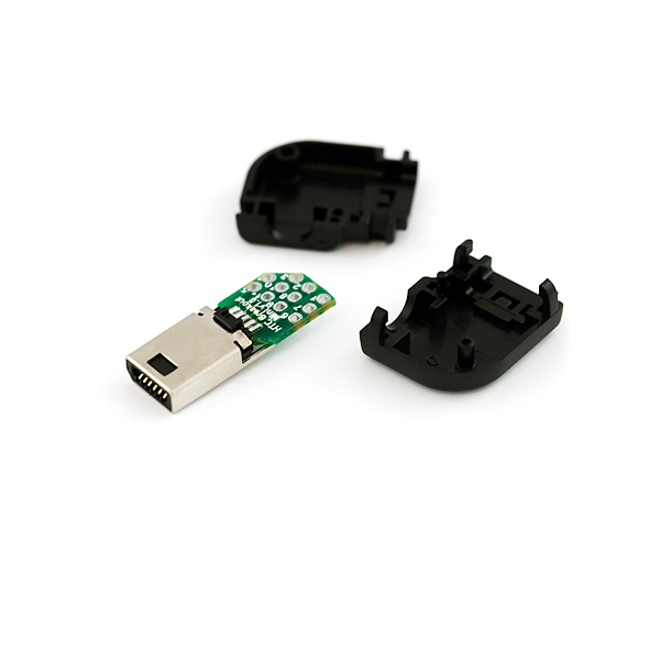
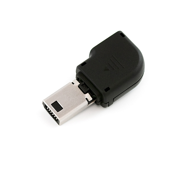
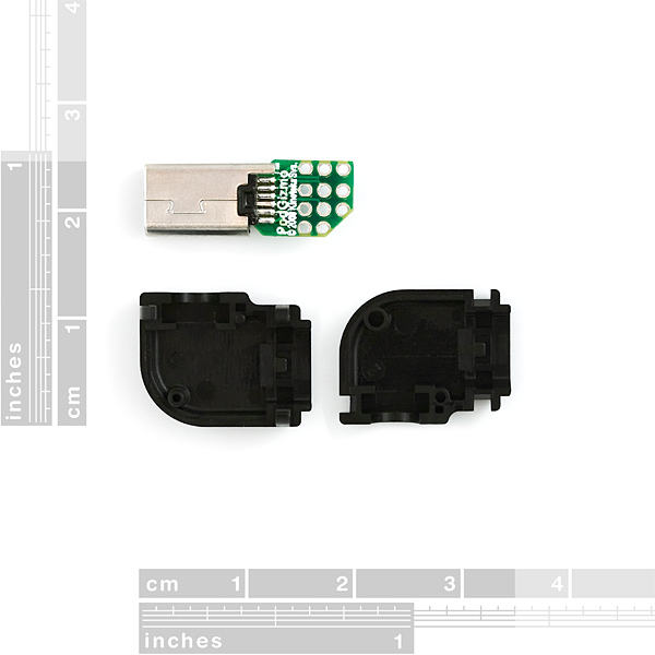
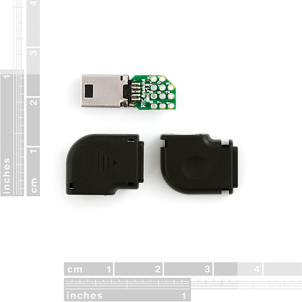
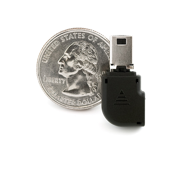
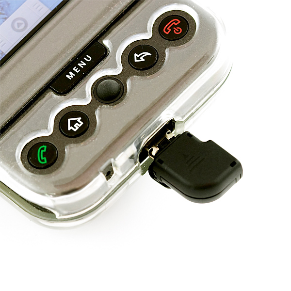
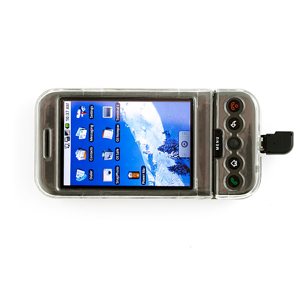
The HTC ExtUSB Breakout pulls all 11 pins from the ExtUSB connector. This board makes it easy to solder wires to the 11 pins and reverse engineer any device that uses the HTC ExtUSB interface. The HTC ExtUSB connector is used on HTC phones like the Android, Orange SPV M3100, HTC TyTN, Vodafone v1605, HTC Oxygen devices and HTC Meteor devices and probably many more. Comes with a snap on enclosure for the breakout board.
To enable audio output, short pins 7 and 8 together.
Check out this Android hack from Instructables.
******Pinout:**
- 1: USB VCC +5v
- 2: USB Data -
- 3: USB Data +
- 4: N / C
- 5: USB GND
- 6: Left Audio +
- 7: Labeled "AG"
- 8: Audio - (GND) Labeled "CK"
- 9: Switch (Talk) Labeled "OT"
- 10: Right Audio +
- 11: Mic +
- 12: Chassis Ground (GND)
- For more pinout information see Kineteka
HTC ExtUSB 11 Pin USB Connector with Breakout Product Help and Resources
Core Skill: Soldering
This skill defines how difficult the soldering is on a particular product. It might be a couple simple solder joints, or require special reflow tools.
Skill Level: Noob - Some basic soldering is required, but it is limited to a just a few pins, basic through-hole soldering, and couple (if any) polarized components. A basic soldering iron is all you should need.
See all skill levels
Core Skill: DIY
Whether it's for assembling a kit, hacking an enclosure, or creating your own parts; the DIY skill is all about knowing how to use tools and the techniques associated with them.
Skill Level: Noob - Basic assembly is required. You may need to provide your own basic tools like a screwdriver, hammer or scissors. Power tools or custom parts are not required. Instructions will be included and easy to follow. Sewing may be required, but only with included patterns.
See all skill levels
Core Skill: Electrical Prototyping
If it requires power, you need to know how much, what all the pins do, and how to hook it up. You may need to reference datasheets, schematics, and know the ins and outs of electronics.
Skill Level: Competent - You will be required to reference a datasheet or schematic to know how to use a component. Your knowledge of a datasheet will only require basic features like power requirements, pinouts, or communications type. Also, you may need a power supply that?s greater than 12V or more than 1A worth of current.
See all skill levels
Comments
Looking for answers to technical questions?
We welcome your comments and suggestions below. However, if you are looking for solutions to technical questions please see our Technical Assistance page.
Customer Reviews
No reviews yet.
Just a quick note about the pinout: here's a fairly complete schematic for the headset, thanks to a fellow on xda-developers.com who tore his apart and documented it. Make careful note of the pinout differences from what's listed in this item's description, however!
Other takes on the pinout:
http://pinouts.ru/PDA/htc_extUSB_pinout.shtml
http://pinouts.ru/PDA/htc_extusb_headset_pinout.shtml (earlier version of above schematic)
http://www.hardwarebook.info/ExtUSB
http://shop.kineteka.com/Products/94-htc-extusb-breakout-mini.aspx
http://shop.kineteka.com/Products/93-htc-extusb-11-pin-usb-connector-style-1.aspx
This product is great except for one thing. the notch is on the wrong side, so you have to break out a precision knife to make it close properly.
Could I just get an extra usb cable and cut the plug off the pc end to interface with myu arduino?
Is there any plan to fix the problem with reversal of the board contours that have been mentioned in the comments, or is it going to stay as-is, requiring modification to fit into the housing correctly?
I can confirm that the breakout board is definitely inverted from what it should be; the slice out of the board should be on the opposite side.
It's not as big of a deal as made out to be above, though; instead of carving the breakout board, simply notch the "keyed" side of the housing out so that the square side fits in it with an sharp knife. Space-age ABS plastics fear my leatherman of doom. :) You have to open it up a little bit on the inside as well; the board slightly interferes with the wire keeper closest to the plug.
You can get away with this because the internal keying of the connector itself is identical on both top and bottom, so once you open up the external key, the connector slips right into place, and you can close the housing.
The caveat, of course, is that your plug now aims left instead of right. As it turns out, that's exactly what I wanted for my application, but YMMV.
So hope this is in stock for free day :D
Pin 4 is used to detect the presence of the wall charger. If you connect that through to the unused port of a mini usb plug, and then plug in the wall adapter, your phone will be able to charge at a faster rate. The usb plug coming out of the wall adapter ties that pin to ground so the phone knows it's safe to pull more current than the usb spec allows.
The pin outs are slightly different on my g1. It appears that pin 7 (labeled AG) is supposed to be analog ground (for mic + audio). When pin 8 (labeled CK) is connected to any ground (pin 5, 7, or 12), audio output is enabled. I believe the labels may point to this, with AG being Audio Ground and CK being Check? I'm still trying to figure out the behavior of pin 9. I can only get it to control the music player. Short press (connection to ground) causes audio to play/pause while long press brings the music app to the foreground.
Yeah, it's a big shame that the breakout board is wrong way around. It ends up being quite useless, $7 difference for a board you have to cut anyway...
Same problem here. I'd recommend getting the breakout-less version. I don't think the pins are too small to hand solder but a comment posted on the other part lead me to order this instead. I think I'll just remove the breakout. I wonder if the pin numbers match up correctly.
Too bad companies like htc, sony and others think they know whats best for their consumers amd use proprietary cables, media, and drm. Glad we have sparkfun around to save us. When you guys call PodGizmo about this issue, tell em to drop the price too ;-)