- Home
- Product Categories
- Kits
- SparkFun Lectro Candle Kit

SparkFun Lectro Candle Kit
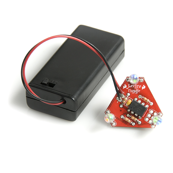
The SparkFun LectroCandle is a simple, through-hole kit, comprised mainly of 3 RGB LEDs and an ATtiny85 to control them. Essentially, the Lectro Candle is exactly what it sounds like – an LED-based “candle” that cycles through all the colors of the rainbow. The programming pins of the ATtiny85 are also brought out on the PCB, so you can customize the firmware however you want. This is a perfect kit to start exploring physical computing and play around with LEDs!
This kit comes as a bag of parts, which you'll need to solder onto the PCB. All components are through-hole, so this kit is great for that first-time solderer. Make sure you install everything with the correct polarity!
Batteries not included!
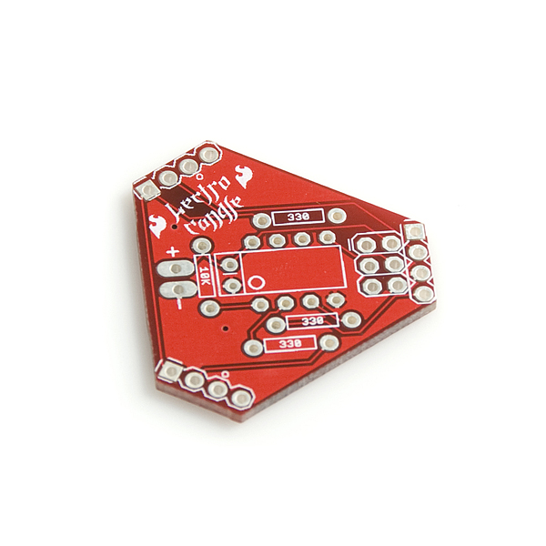
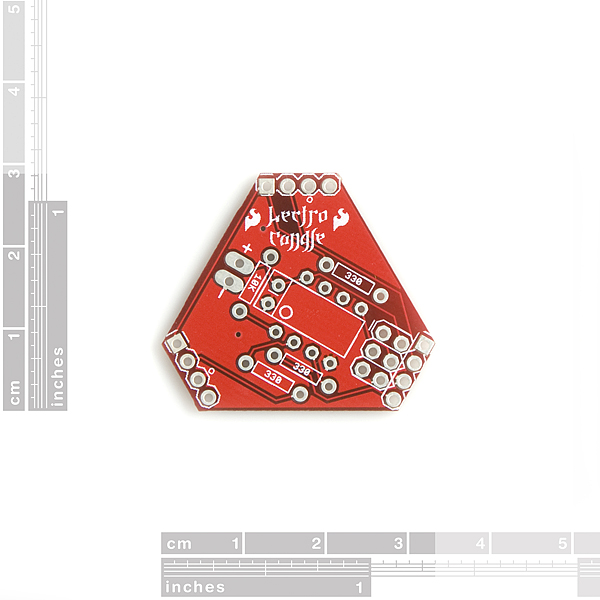
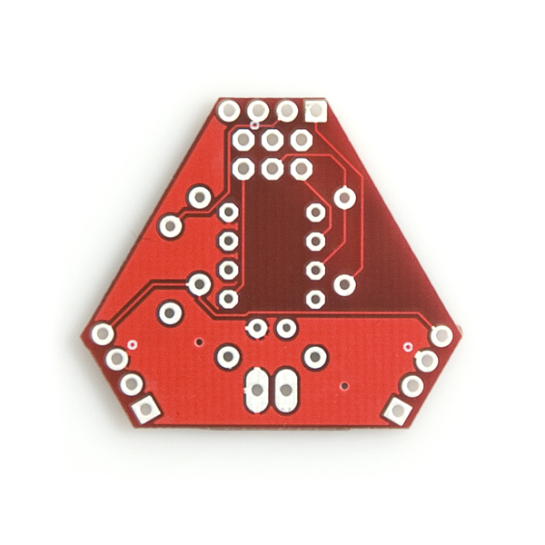
- 1x Lectro Candle PCB
- 1x ATtiny85 - Programmed for Lectro Candle
- 1x 2xAA Battery Holder with Cover and Switch
- 3x RGB LEDs
- 1x Resistor - 10KΩ
- 3x Resistor - 330Ω
- 1x 0.1uF Ceramic Capacitor
SparkFun Lectro Candle Kit Product Help and Resources
Core Skill: Soldering
This skill defines how difficult the soldering is on a particular product. It might be a couple simple solder joints, or require special reflow tools.
Skill Level: Rookie - The number of pins increases, and you will have to determine polarity of components and some of the components might be a bit trickier or close together. You might need solder wick or flux.
See all skill levels
Core Skill: Electrical Prototyping
If it requires power, you need to know how much, what all the pins do, and how to hook it up. You may need to reference datasheets, schematics, and know the ins and outs of electronics.
Skill Level: Rookie - You may be required to know a bit more about the component, such as orientation, or how to hook it up, in addition to power requirements. You will need to understand polarized components.
See all skill levels
Comments
Looking for answers to technical questions?
We welcome your comments and suggestions below. However, if you are looking for solutions to technical questions please see our Technical Assistance page.
Customer Reviews
No reviews yet.
Is that the correct source code? For one there are 3 other .c files for er... cat feeders it seems.
Also, it looks like the LEDs only cycle each LED colour on and off with a 400ms delay. Seems a waste not to cycle through, well, more colours.
I just made an RGB nightlight for my kids which goes through a few million colours. You could steal my source code and apply it to this kit if you want. I used an ATtiny13 and common anode RGB LEDs so the code wouldn't need that much tweaking:
http://fangletronics.blogspot.com/2010/02/rgb-night-lights.html
yeah, seconded...someone didn't clean out that folder before zipping it up...
Well, to add to everyones previous comments, I didn't read the source code until AFTER I ordered 15 of these for a training class. I just put one together and it certainly doesn't emulate a candle (lol, not that I expected it too) but I did expect color fading and there is none. It runs amok. Looks like I am going to have to solder headers on one of them and bust out the C code. I will try Paul B's code with some tweaking. Fortunately I am using them for soldering practice. I did buy 60 Tiny Cylons too but could not get 75 at the time so I bout 15 of these. Keep ya posted. but this isn't high on my to do list...
i am new to this kind of thing so how would i go about connecting the lectro-candle to my computer so that i can modify the code?
You will need some headers to solder onto the board's 6 ISP pads (it's the group of 3x2 pins together), and then you'll need an AVR programmer. See Pocket AVR Programmer for more information (be sure to read the comments as well).
.
Got this to replace a damaged circuit in a christmas tree angel. The flicker rate on this is way too high, and there's no color fading. Not very candle-like, really. It does appear that it's reprogrammable. I'm going to attempt to reprogram it using an Ard Nano as an in-system programmer and see if the result is any more useful, I hope that it is, otherwise I'll be feeling pretty gypped.
First for the complaint, I have to say that the plain candle was not so exciting. Second for a Great! I took the plain LEDs and replaced them, with 0805 SMT LEDs in red, amber and yellow (630, 610 and 590 nm wavelengths, 10 - 20 ma rating) soldered on 32 gauge wire about 2 feet long. Caution, green LEDs can be a problem for 3 volts, blue is out of the question. I only go up to yellow green (574nm) but red yellow amber works out better visually too. Now I have a cloud of lights (well, 9 anyway), each light the size of a grain of rice! My wife loves it. I had to make another for her. Soldering SMT on magnet wire can be tricky. Tin the wire first. I use clear nail polish on the LEDs to make sure it does not short out in case it some in contact with metal. Batteries (fresh AAs) last over a week. In this case the random light changes makes for a better effect.
It's a pity that - based on the comments - this kit needs more polish. An electric candle which is RGB, random colors, and no button to toggle modes? You can already get candle flasher LEDs which proudly flaunt unnatural candle flicker and color.
A candle kit is an IDEAL ATtiny tutorial platform, but it looks like the only concept this can offer is soldering.
Just built one and noticed the lights were dim and blue not even illuminating. Measured my batteries and they were only putting out about 2.2V. Hooked up a 3 volt power supply and now it works great with all 3 colors and nice brightness. Definitely get fresh batteries.
If I may make one tiny suggestion for any possible future revision:
I see you've two spare pins on the micro - 5 and 6. If the blue LED channel was driven from pin 6 instead of 7, you'd have 5 and 7 free, which would enable I2C communication with the board (and these pins are ever so conveniently broken out for you already, right in the middle of the ISP header). A little custom code and you'd have a nice little I2C controllable blinky.
I built two of these and reprogrammed them with Paulb's code edited for the Atiny85. I do not have the green led's working at all on either kit. Have not finished troubleshooting so don't know if I screwed something up or if there is something else going on. The default software really is useless... The only code changes I needed were the pin assignments (The green LED's did not work before I reprogrammed...) and the interrupt enable is "TIMSK =" not "TIMSK0 ="
Two things, can you post the code you used and bow you did it. Second increase your vcc, on mine the blue was not working so I went to 3 batts and everything worked great
When I first read the name of the kit, I was thinking COOL a 3 LED artificial candle kit!
Maybe like this one http://www.enjoylighting.com/lantern.htm
Then I read RGB and I thought cool a kit that fades though the rainbow of colors.
But when I tested the code, it seams to just strobe all leds at an epileptic rate... ???
:(
I hear ya, it just scrolls through the colors boringly.