- Home
- Product Categories
- Modules
- GPS Receiver - Retail LS20031 5Hz (66 Channel)

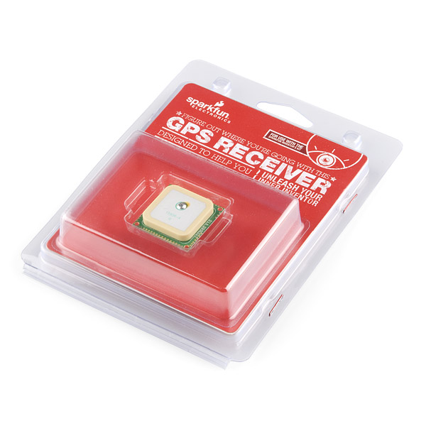
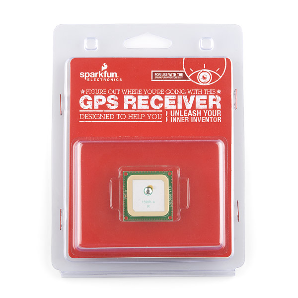
GPS Receiver - Retail LS20031 5Hz (66 Channel)
Description: The LS20031 GPS receiver is a complete 10Hz GPS smart antenna receiver, that includes an embedded antenna and GPS receiver circuits. This low-cost unit outputs an astounding amount of position information 5 times a second. The receiver is based on the proven technology found in LOCOSYS 66 channel GPS SMD type receivers that use MediaTek chip solution.
The GPS smart antenna will track up to 66 satellites at a time while providing fast time-to-first-fix, one-second navigation update and low power consumption. It can provide you with superior sensitivity and performace even in urban canyon and dense foliage environments. The capabilities meet the sensitivity requirements of car navigation as a well as other location-based applications.
This module makes a great gift for that special someone who's interested in playing with GPS. For more gift ideas check out the SparkFun Gift Guide!
**Note: **The datasheet for this unit states that the update rate is configurable up to 10Hz but we've found that it is most reliable at the default rate of 5Hz.
Note: The new version of this module uses the MT3329 MTK chipset.
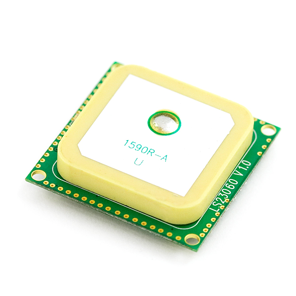
Note: Unit does not contain a connector, however there are 5 bare pads you can solder to. Check out our tutorial on how to solder a right-angle 5-pin header to the pads. It's easier than you might think.
Note: Hacking makes the world go 'round, but be careful if you decide to flash some 3rd party firmware to this module because we cannot get the original for you. If 3rd party firmware breaks your device, according to the manufacturer, you're on your own!
Check out our GPS buying guide!
- MediaTek MT3318 solution
- 5Hz output
- 57600bps TTL serial interface
- 3.3V @ 41mA
- 66 Channel GPS
- Fast TTFF at low signal level
- Up to 10Hz update rate
- Capable of SBAS (WAAS, EGNOS, MSAS)
- Built-in micro battery to preserve system data for rapid satellite acquisition
- LED indicator for fix or no fix
- Datasheet
- PMTK Protocol Reference
- Great configuration software: Mini GPS
- Example Configuration from DIYDrones
- Connection Tutorial
GPS Receiver - Retail LS20031 5Hz (66 Channel) Product Help and Resources
LS20031 5Hz (66 Channel) GPS Receiver Hookup Guide
December 13, 2018
In this tutorial, we will solder headers to the surface mount pads of the LS20031 GPS receiver and read the output using an Arduino!
Core Skill: Soldering
This skill defines how difficult the soldering is on a particular product. It might be a couple simple solder joints, or require special reflow tools.
Skill Level: Competent - You will encounter surface mount components and basic SMD soldering techniques are required.
See all skill levels
Core Skill: Programming
If a board needs code or communicates somehow, you're going to need to know how to program or interface with it. The programming skill is all about communication and code.
Skill Level: Rookie - You will need a better fundamental understand of what code is, and how it works. You will be using beginner-level software and development tools like Arduino. You will be dealing directly with code, but numerous examples and libraries are available. Sensors or shields will communicate with serial or TTL.
See all skill levels
Core Skill: Electrical Prototyping
If it requires power, you need to know how much, what all the pins do, and how to hook it up. You may need to reference datasheets, schematics, and know the ins and outs of electronics.
Skill Level: Competent - You will be required to reference a datasheet or schematic to know how to use a component. Your knowledge of a datasheet will only require basic features like power requirements, pinouts, or communications type. Also, you may need a power supply that?s greater than 12V or more than 1A worth of current.
See all skill levels
Comments
Looking for answers to technical questions?
We welcome your comments and suggestions below. However, if you are looking for solutions to technical questions please see our Technical Assistance page.
Customer Reviews
No reviews yet.
I guess max is 30/2 at most !
One warning if you solder the 90 degree header pins to the pads as depicted in the Connection Tutorial: I went this route, then installed the unit on a breadboard. Worked flawlessly while designing circuit. Once things were working I removed it from the breadboard so I could mount it permanently. Unfortunately just the pull on the pin from this removal was enough to lift one of the ground pads; it took me a while to spot what was going on. I was able to apply a greenwire 'fix' by soldering a jumper from the remaining pad to a bit of trace I exposed with an xacto, but still kind of a shame; now I have to order another one because I don't trust my connection will stand up to abuse. Next time I'll mount it on standoffs and just solder a cable in place.
This GPS module has an protection diode in case of wrong power supply connection.
I've discovered this yesterday, when i mistakenly connected Vcc and GND of power supply to GND and Vcc (respectively) on module.
Doh SF, we all know what the top looks like! How about an image of the bottom; with the connectors :D!
I've compiled a good bit of info about this GPS and posted it to the Dallas Makerspace wiki.
I noticed someone was looking into using it on a near space balloon? Does that mean it's capable of functioning above the 18km civilian limit?
Was it ever confirmed that someone used the GPS module succesfully above the 18km limit?
I'm planning on using a GPS module on a satellite project for a Cubesat in a low earth orbit of 800km. This information would be key to me specifying a GPS module to use.
It's up and playing nicely with a PIC16F887 (although I'll be moving to a faster MCU soon, because reading data from this thing with the MCU running at only 4 MIPS is like trying to drink from a fire hose, even at the default 5Hz.) Caveat programmor: the default baud rate is 57600/N/8/1, not 9600/N/8/1 as stated in the datasheet. (It has to be.) It runs on up to 4.2V, so I have it running from one of SparkFun's Li-Ion batteries. The GPS/PIC/LCD combo draws about 40-50mA with the backlight off. Not bad!
So am missing something? "5 times a second" but "10Hz" Also in the bullet list you have "5Hz output" and "Up to 10Hz update rate".
Datasheet says they updated it from 5Hz to 10Hz.
"will track up to 66 satellites at a time"
Yeah - good luck with that given there are only 30-something GPS satellites total on the orbits ;)
My first guess would be Galileo because that uses the same frequency as GPS L1 but it does use a different modulation system so probably not. Probably just future proofing.
The "track up to 66 satellites at a time" claim is bogus - that's not what all those channels are for.
When you cold-start the device it doesn't know the time, it doesn't know where on the earth it is, it doesn't know the ephemeris data of any of the satellites, and it doesn't know the doppler shift of the satellites and it doesn't know the doppler shift of you (you may be moving in a vehicle). So it starts to scan. The way to do that is to listen to some frequencies for a while, then shift frequencies and listen for more. Until it finds at least one satellite. Then it has to wait for the almanac data to come around (imprecise ephemeris data for all the satellites) which only happens occasionally and may take half a minute to receive all of it).
All of this goes much faster if you can listen to a great many channels at the time. A 12-channel GPS receiver will listen with 12 channels, then change frequencies and listen to another set of frequencies. A 66-channel, or even 48- or 32-channel receiver can search, find, and acquire almanac data (which is used to then find each individual satellite and acquire its satellite-specific precise ephemeris data) much quicker. That's why these megamulti-channel GPS receivers can basically guarantee to go from cold-start to lock in < 35 seconds, while an old 12-channel receiver as the SiRF Star II could take much longer, and wouldn't lock at all if you're not standing still while searching (it doesn't have enough channels to afford dedicating some of them to be set up for doppler shifts). The newer SiRF Star III has many more channels than my old Star II. Likewise the MTK chipset I'm using now, it doesn't need you to stand still while searching - it locks fine even when flying at high altitude inside a 747. In fact the 66 channels of this LS20031 seems a bit of overkill when compared to how well the 30-48-channel receivers work.
This receiver is capable of WAAS, so you aren't just listening to satellites.
Not sure what you mean by this comment. WAAS signals are broadcast from 2 satellites in geosynchronous orbit over the equator. The correction information is generated at various ground stations around North America -- but is then up-linked to the WAAS satellites for broadcast.
http://en.wikipedia.org/wiki/Waas
LOL - Currently in orbit
and healthy: 30 :) , planned total 59 (2014-xxxx)