- Home
- Product Categories
- 7-Segment
- 7-Segment Display - 4-Digit (Blue)

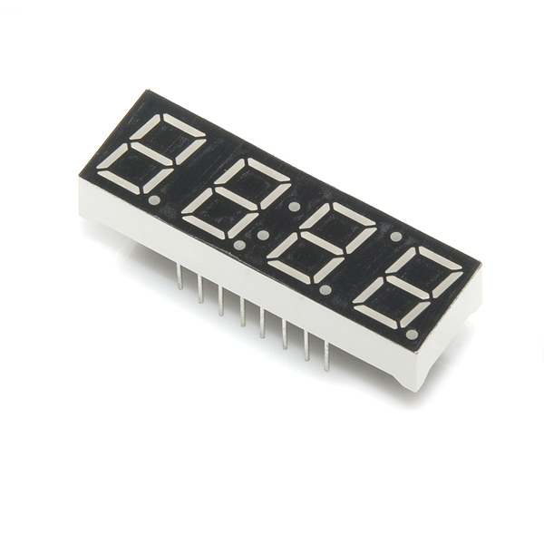
This is a basic, 4-digit 7-segment display - blue in color. It has a common anode. The display features one decimal point per digit, and individually controllable apostrophe and colon points.
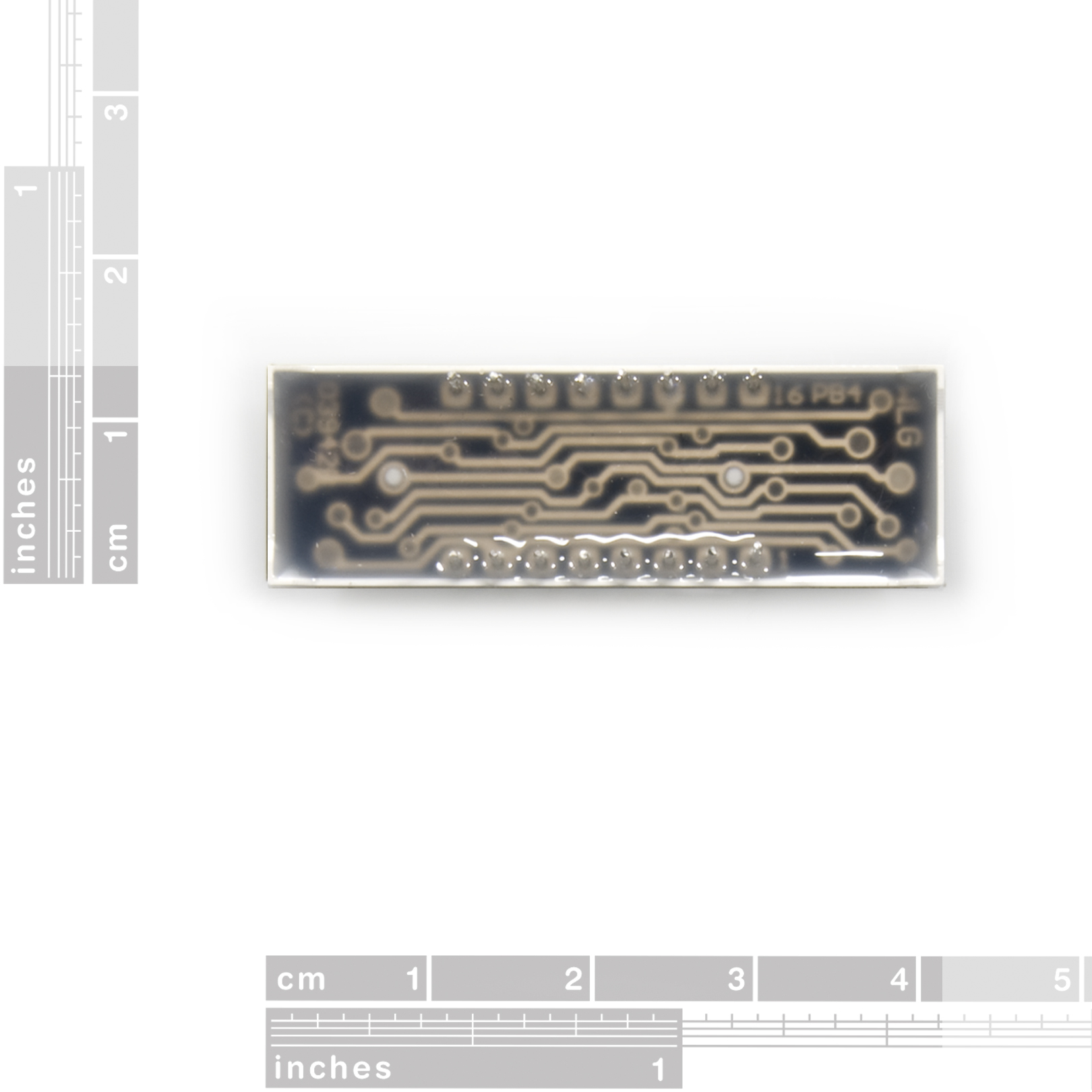
The LEDs have a forward voltage of 3.4VDC and a max forward current of 20mA. The hardware interface is sixteen (two rows of eight) through-hole pins.
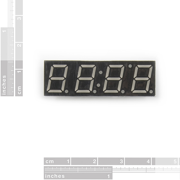
- Overall Display: 40.18 x 12.8 mm (1.58 x 0.50")
- Digit Height: 10mm (0.39")
7-Segment Display - 4-Digit (Blue) Product Help and Resources
Core Skill: Electrical Prototyping
If it requires power, you need to know how much, what all the pins do, and how to hook it up. You may need to reference datasheets, schematics, and know the ins and outs of electronics.
Skill Level: Competent - You will be required to reference a datasheet or schematic to know how to use a component. Your knowledge of a datasheet will only require basic features like power requirements, pinouts, or communications type. Also, you may need a power supply that?s greater than 12V or more than 1A worth of current.
See all skill levels
Comments
Looking for answers to technical questions?
We welcome your comments and suggestions below. However, if you are looking for solutions to technical questions please see our Technical Assistance page.
Customer Reviews
No reviews yet.
If anyone wants some extra code or wants do make a clock with an arduino I made a project on instructables with this display
http://www.instructables.com/id/TimeDuino-Arduino-based-clock-using-7-segment-dis/
You can't charlieplex the display due to a single common anode. If you want to be able to control all the lights, you will need like 14 pins to do so.
In theory you could drive a display like this with just 5 pins if it was made out of individual LEDs.
I bought this over three years ago and finally have a use for it! I wish at the time I had understood that common anode meant that it wouldn't be compatible with the MAX7219 I bought with it Oh well, gives me an opportunity to use more of the ATmega pins and do it manually.
Speaking of which, Nate's 2011 driver code seems like a great start, especially since it doesn't require any resistors. I understand that with fast enough PWM, the LEDs are not on long enough to burn out, but is that also true for sinking or sourcing current from an ATmega pin? i.e. Does this design not require any transistors on the digit pins either? If a pin has a max rating of 40mA, won't the digit pins be sourcing more than that, especially if they are displaying a number 8 for example? In the notes, he says that turning each digit on for 5000 microseconds will draw 15.7mA, but I don't understand how that number is calculated. Thanks for any help!
Can this display be controlled by a Arduino Pro Mini 328 - 3.3V/8MHz? Does the 3.3V arduino board have enough power to drive it?
Why is the white $1.95 and the blue $2.50? The white is basically a blue with a white filter over it. (If you look at the back of the white one when it's on, you can see it glowing blue.) So it cost's 55 cents more to not put the filter on it??
Hi, I have been using the Serial_7_Segment_Display_Firmware sketch, and I cannot make any sense of the output.
When I run the code as-is, my display looks like this: http://imgur.com/UmmWysg
I have tried a lot of things, including replacing my loop to display a whole bynch of ints, none of which I can make sense of on the display. There are a few segments that never light up. Is my display broken? Is there a coding solution to this problem?
Thanks
Fellow 13375, hackers, and hobbyists- These displays ROCK! after utilizing them in several prototypes, i only had 1 gripe-THE WIRES! Between multiplexing the segments together, power, and communication - it can get pretty ridiculous, ergo, i humbly submit for your approval, my contribution to the cause.
http://www.kickstarter.com/projects/813180812/8-digit-7-segment-breakout-board Here's to Open Hardware. If you wanna grab a copy of the eagle files i can get you a link. -b3457
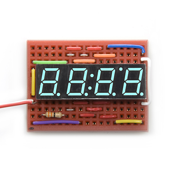
This is what it looks like in action (direct-driven, w/ 330 Ohm resistors):
http://www.youtube.com/watch?v=HbTW_QWEx6s
anyone know he manufacturer part number?
YSD-439AB4B-35. It's in the datasheet.
These are very clear and easy to use, for a demonstration please visit: http://wp.me/pQmjR-zL
Turinturambar88,
Thanks for the great info. I did manage to get this working and your advice is dead-on.
I have posted my code and so have a few others on my arduino forum topic here:
http://www.arduino.cc/cgi-bin/yabb2/YaBB.pl?num=1265669651
Hey sparkfun and community,
I was wondering if anyone could direct me to a good tutorial for using these particular displays.
Or could someone who got them working please provide some sample code and description of schematics?
Thanks!
ahmad,
I just got one of these in the mail, and I'm starting to get it to work. I'm using an atmega48, and I connected PORTD to the display with LED_A-PORTD0...LED_G-PORTD6. You can find a table of bit encodings at the bottom of http://en.wikipedia.org/wiki/7_segment_display and store them in an array (use the gfedcba column, but invert the values because the display is common anode, i.e. led_digits[0] = ~0x3F;). If you set PORTD to one of those values, and then set one of the Digit # pins on the LED high, you should see that value on that digit. You'll have to rotate through turning the different digits on and off quickly to set different values on each. I'm new at this, so if there's a better way I'd love to know, but hopefully this helps some.
they really need to dump this on one of those serial display boards w/ the atmega168
not compatible with the Capacitance Meter DIY Kit X_x as i just found out