
Controllable Power Outlet
Controlling Big, Mean, Devices
Microcontrollers are a ton of fun. Once I got hooked, there was no
turning back. Initially playing with sensors and LCDs, I quickly
discovered the limits to what a microcontroller could control. A microcontroller's GPIO (general purpose input/output) pins cannot handle higher power requirements. An LED
was easy enough, but large power items such as light bulbs, toaster ovens, and blenders required more sneaky circuitry. Something sneaky called a relay:

In this tutorial we will discuss a small relay board to control the power to a normal AC outlet using 5VDC control.
What's a relay?
I admit, I really just wanted to build my own Blender Defender (I don't even have a cat!). However, building a 5V controllable outlet can be handy for many applications. For these power hogs, a relay is the perfect fit.
A relay is a large mechanical switch. That switch is toggled on or off by energizing a coil.
In this example we are going to talk about the simplest version of a relay. Inside the relay are two paddles made of metal. One paddle is made of a ferrous material like steel and is free to move. The other paddle is made of copper and stationary. When these paddles touch (the closed switch state), they are capable of allowing a large amount of power to flow - like 30A@120VAC (huge!).
The other half the relay is called the coil. This is basically a small electro-magnet. If you send current through the coil, a magnetic force is created, which pulls on the steel paddle causing it to move (flip) and touch the copper paddle - as if you flipped a light switch. The coil requires a small amount of power (5VDC @ 80mA). So you see, controlling the low-power coil allows us to actually control quite a lot of power!
It is important to note the coil is physically isolated from the paddles. If you have 120VAC running through the paddles, you don't have to worry about that 120VAC sneaking back into and vaporizing your microcontroller (connected to the coil).
The paddles are capable of carrying very large currents. Both AC or DC - the paddles don't care. A relay can be used to control a DC motor, or an AC lamp.
The relay that we will be working with, in this tutorial, is a beefcake in my opinion. It can handle a lot of power - 30A at 220VAC. What happens if you violate this limit? I have thankfully never been in that situation. I have heard reports that the relay will begin to heat up. When the voltage/current becomes large enough, there will be sparks inside the relay as you switch the paddles. If these sparks get large enough, you can actually spot weld the movable paddle to stationary paddle causing the relay to fail, potentially in the 'on' position. Obviously this would be very bad on many levels.
Like we do with capacitors, we under-rate the relay so that we mitigate the risk of relay failure. If you need 10A@120VAC, don't use a relay rated for 10A@120VAC, instead use a bigger one (such as 30A@120VAC). Remember, power = current * voltage so a 30A@220V relay can handle up to a 6,000W device (two hair dryers).
The Outlet

All the usual warnings apply: Main voltage (120VAC or 220VAC) can kill you. This project, done incorrectly, could certainly burn down your house. Have your pet spayed or neutered. Shampoo is better. Do not work on or solder to any part of a project while it is plugged into the wall - just unplug it!
You can get the Eagle files for the control board here. The control board is composed of a relay along with a NPN transistor and LED.
What's a relay?
I admit, I really just wanted to build my own Blender Defender (I don't even have a cat!). However, building a 5V controllable outlet can be handy for many applications. For these power hogs, a relay is the perfect fit.
A relay is a large mechanical switch. That switch is toggled on or off by energizing a coil.
In this example we are going to talk about the simplest version of a relay. Inside the relay are two paddles made of metal. One paddle is made of a ferrous material like steel and is free to move. The other paddle is made of copper and stationary. When these paddles touch (the closed switch state), they are capable of allowing a large amount of power to flow - like 30A@120VAC (huge!).
The other half the relay is called the coil. This is basically a small electro-magnet. If you send current through the coil, a magnetic force is created, which pulls on the steel paddle causing it to move (flip) and touch the copper paddle - as if you flipped a light switch. The coil requires a small amount of power (5VDC @ 80mA). So you see, controlling the low-power coil allows us to actually control quite a lot of power!
It is important to note the coil is physically isolated from the paddles. If you have 120VAC running through the paddles, you don't have to worry about that 120VAC sneaking back into and vaporizing your microcontroller (connected to the coil).
The paddles are capable of carrying very large currents. Both AC or DC - the paddles don't care. A relay can be used to control a DC motor, or an AC lamp.
The relay that we will be working with, in this tutorial, is a beefcake in my opinion. It can handle a lot of power - 30A at 220VAC. What happens if you violate this limit? I have thankfully never been in that situation. I have heard reports that the relay will begin to heat up. When the voltage/current becomes large enough, there will be sparks inside the relay as you switch the paddles. If these sparks get large enough, you can actually spot weld the movable paddle to stationary paddle causing the relay to fail, potentially in the 'on' position. Obviously this would be very bad on many levels.
Like we do with capacitors, we under-rate the relay so that we mitigate the risk of relay failure. If you need 10A@120VAC, don't use a relay rated for 10A@120VAC, instead use a bigger one (such as 30A@120VAC). Remember, power = current * voltage so a 30A@220V relay can handle up to a 6,000W device (two hair dryers).
The Outlet

The goal is the get a GFCI outlet into some sort of a housing, with a power cord, the relay, and control circuitry.
Materials:
Truthfully, the GFCI may only shut off when there is a current leak across a connection to ground - and not an over-current condition. What this means is if your 'project' suddenly pulls 50A because the microwave turned on, the GFCI will not trip off. But it you accidentally touch the wrong exposed wire, the GFCI will trip because it will detect a fault to ground (saving your heart from cardiac arrest). We repeat - when working on any part of an AC project, unplug the thing from the wall.
The Inline Power Control Board
The first thing you need to do is build up the Power Control board.

The Build
Take that beautiful extension cord and cut off the female connector about 6" from the female end.

A male US power plug next to the cut off end of the extension cord
Materials:
- GFCI Outlet ($10)
- Nail mount housing ($1)
- Thick 3-wire type extension cord, 8 feet (2-wire cords will not work) ($7)
- Relay ($4)
- Control board and parts ($5)
Truthfully, the GFCI may only shut off when there is a current leak across a connection to ground - and not an over-current condition. What this means is if your 'project' suddenly pulls 50A because the microwave turned on, the GFCI will not trip off. But it you accidentally touch the wrong exposed wire, the GFCI will trip because it will detect a fault to ground (saving your heart from cardiac arrest). We repeat - when working on any part of an AC project, unplug the thing from the wall.
The Inline Power Control Board
The first thing you need to do is build up the Power Control board.
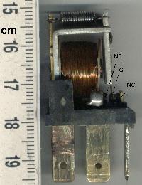
This board contains the relay, transistor, and activation LED. The board requires 5V and GND to operate. A control pin controls whether the relay is 'closed' (allows high power to flow) or 'open' (paddle's default state of disconnected).
The control board is fairly straight forward. The coil within the relay requires up to 80mA. This is more than a GPIO pin can handle (20mA by default) so we use NPN transistor as a controllable connection to ground. The NPN transistor can handle up to a 200mA which is more than the coil (80mA) and the LED (20mA) combined.
When the 'RELAY' pin (aka CTRL) goes high, the NPN transistor connects to ground sending current through the coil (activating the relay) and through the LED (turning the activation LED on). R1 pulls the 'RELAY' pin to ground so if anything goes haywire the relay will remain in the safe, off position.
Note: The 1N4148 diode is connected in a odd fashion for a reason. This is placed between power and ground in a reverse fashion. When the coil of the relay is de-activated, it acts like an inductor, trying to suppress current change. This can cause some havoc on the 5V power rail. When this happens, the 1N4148 will forward bias causing the current stored in the coil to flow happily back to the 5V rail protecting the power supply and the near-by parts.
The Build
Take that beautiful extension cord and cut off the female connector about 6" from the female end.

A male US power plug next to the cut off end of the extension cord
This should leave leave a few feet of extension cord between the part that plugs into the wall (male end) and the bare, exposed, recently cut-off end of the extension cord. Don't plug it in!
Note: A two-wire extension cord will not work correctly. Notice we are using thick, three-wire circular extension cord. This extra wire is the ground return and allows the GFCI to operate correctly.
Using a meter set to continuity, check that the ground pin (the round one) is indeed connected to the green ground wire. I've seen a few extension cords with non-standard colors.

Use a wire stripper or an exacto-knife to remove about 6" of the sheath from the extension cord. You should find three wires - black, white and green.


Use wire strippers to strip the three wires individually about 1". I twist the ends of the wires to combine the strands of the wires together in preparation for soldering.


Notice the hooks on the three wires. I wrapped the tinned ends of wire around a small jewelers screw driver to create a half circle within the wire. This will aid connection to the screws on the GFCI.

Sometimes the roll of solder can be used as a third hand.


The goal here is to 'tin' the three wires. Adding solder to each of the stranded wires will hold all the wires together and allow for easier manipulation later.

Be sure to thread the extension cord through the housing (shown above) before soldering to the control board. It's a huge pain to have to cut and remove the wires from the control board.

Be sure to thread the extension cord through the housing (shown above) before soldering to the control board. It's a huge pain to have to cut and remove the wires from the control board.

Be sure the extension is threaded through the housing before you do this step.
With a good 6" of wire exposed, cut the black wire about 5" down from the end. The is where the relay will live.
With a good 6" of wire exposed, cut the black wire about 5" down from the end. The is where the relay will live.

Notice the hooks on the three wires. I wrapped the tinned ends of wire around a small jewelers screw driver to create a half circle within the wire. This will aid connection to the screws on the GFCI.
Here we have the black wire cut and soldered to the control board. The relay is a NO (Normally Open) type relay. When power is off, there is no connection between the two thick black strands that you just cut and soldered. This is a safety feature - if all things go wrong and the power goes out of the coil, the relay will kick off and the outlet will shut down.
Conversely, when you send 5V to the coil, the paddle flips from the 'off' state to the 'on' state, connecting the two pieces of black wire (on the left side of the picture above), power is delivered to the outlet and your project is powered.

Now we connect the wires from the extension cord to the outlet. The Black and white wires connect to the two side terminals of the GFCI - the green wire (ground) connects to the end of the outlet.
Advanced trick: Notice how the hooks of the tinned wires are arranged so that they are clock-wise. If you align the hooks of the wires under the screws correctly, as you tighten the screws, the hook of the wire will be 'sucked' into the tightening screw. This creates a very compact connection.

Now lower the relay into the enclosure and feed the control wires (red, yellow, and black) out one corner of the housing. (You're right, the extension cord wires are not soldered to the relay board in this picture - please make believe).

You can double-stick tape the control board to the bottom of the housing or just let it float - the wires from the extension cord will tend to hold it in place. Once you have everything lowered into place, screw the outlet onto the enclosure, and the face plate onto the enclosure.

Here we test the controllable outlet against the Boxing Timer

Here we test the controllable outlet against the Boxing Timer
DO NOT plug the extension cord into the wall yet.
Now for the moment of truth. Attach the three control wires (5V, GND, and CTRL) to some sort of system. In the above picture, I have a fairly dirty breadboard. All that I am actually using on the bread board is 5V and GND - ignore all the other parts as they are not doing anything. I then manually toggled the control wire from GND (off) to 5V (on). You can do the same thing by plugging into the 5V and GND pins on an Arduino board.
Tying the CTRL line to 5V I heard a very friendly click as the relay kicked over. This indicated (along with the LED on the control board) that the relay was actuated to the 'on' position. Removing CTRL from the 5V rail (called floating because the CTRL line is neither connected to 5V or GND), the relay released. This is good! If CTRL is left floating or tied to ground, the outlet is turned off.
You can also use a meter in continuity mode to check that the relay is working properly before you connect to 120VAC. When the relay's open, one of the fins of the plug and one of the rectangular holes of the outlet will not have continuity, and when it's closed, they will. The other fin and rectangular hole will always have continuity, as will the ground pin and the funny hole. I always do this check before plugging into the 120VAC, because I am, you know, paranoid.
The next step is to plug the extension cord into the wall and test again. If anything goes wrong the GFCI should activate and cut off. Be sure to unplug the outlet anytime you are working on it. Please don't get zapped!
You should now have an outlet that is fully controllable over 5V logic. When you plug a device into the outlet, it will by default be off. When you expose 5V to the CTRL line, the relay will activate turning on power to the device plugged into the outlet.
Enjoy!
Nathan Seidle
How did you figure out the relay coil requires 80mA at 5VDC?
From what I am finding in both the Datasheet and specs listed at DIGIKEY it is a 200mA coil at 5VDC.
Actually,
Bear and Solar, I am a Electrician with 17 + years experience, and you can pass low voltage and high voltage through, in or out of the same enclosure, raceway, etc. as long as both conductors are rated for the same voltage, ie.;
THHN commonly used for commercial and industrial wiring is rated for 600v. It can be used for both low and high voltage. Most wire we use in electronics is rated at 300v, if this wire is in the same raceway/enclosure as 600v rated wire, then there simply needs to be a divider separating the wire.
I think your point only applies to low-voltage and high-voltage wires running together in the same enclosure or raceway without any splices. There, adequate insulation protects against accidental shorting between the conductors. But in a box with splices (like this), I believe the code requires a barrier between the high-voltage and low-voltage components. The risk here is if a high-voltage conductor comes loose and touches the exposed end of a low-voltage conductor -- you will send high voltage out on the low voltage lines which could cause damage, fires or electric shock. There is a provision that allows high and low voltage if the high voltage is there only to provide power to the low voltage device, and maybe if the low voltage is there to control the high voltage (I still need to double-check that). In that case, the requirement is that no other high voltage wires be in the box, and the high and low voltage conductors need to be 6 mm apart. So this may just get by...
Some people want a SPDT relay. You can re-layout the pcb to include the SPDT relay footprint. However, the NC contacts are rated much lower than the NO contacts. I would recommend the 1.0W relay, since it also has ballast and tungsten ratings. The ballast ratings are for magnetic (transformer types), not for electronic ballasts unless otherwise stated. An electronic ballast can have as much as 10 times the in-rush current of magnetic (because electronic ballasts are capacitive), so derate appropriately. If you re-layout the PCB, be sure the traces can handles the current that the relay contacts can pass. I agree with the author for not using the SPDT and don't personally recommend using it or find a relay that has the same 30A ratings on both the NC and NO contacts. For those that like to program, try using a latching type relay in this same footprint. They typically have a much higher current rating. You just need to pulse the coil ON and pulse them OFF to LATCH and UNLATCH them.
The 1K Ohm for the LED was probably chosen, because the LED is a high brightness type. Also, the LED is mounted inside an enclosure an will not typically be seen by anyone. So, the author probably felt the LED necessary, but didn't need it too bright or to consume more power than needed for his project. At 5VDC, the froward voltage of the LED is 3.4VDC max, which gives 1.6VDC remaining. 1.6VDC/1K Ohm = 1.6mA, bright enough for the high brightness variety. If the absolute maximum current is desired, then 1.6VDC/20mADC = 80 Ohms. Personally, I'd either get rid of it or stay with the 1.6mA the author designed the circuit for.
I would recommend using a PN2222 or PN2222A, since these have the same pinout, package and can sink 600mA. Looking at absolute maximum for the relay (the 1.0W relay) and the maximum 20mA (if a tech wants theirs brighter) LED, that gives 220mA on a 200mA rated component. The PN2222(A) have roughly the same voltage ratings, have the same pinout and use the plastic TO-92 case. Probably cost about the same too! The values for R1 and R2 can stay the same.
It's probably worth mentioning that you are putting the relay across the active, hot or live line in the extension cord, which may be black, red, brown or even blue depending on your country and region.
http://en.wikipedia.org/wiki/Electrical_wiring#Color_code
Agree ! I was thinking why did you choose to cut the black and not the white one. I imagine it is because if you are interrupting the white one then if you put your finger in the outlet, even if the relay is open, you will get a discharge, while by interrupting the black one, when the relay is open nothing will happen if you touch the outlet.
Excellent instructable. Finally got around to building it and it works great.
However, I'm struggling with an implementation of the board. I'm using a 3.3 device that has in internal regulator that takes 9v as input. It also has pins that passes the raw input voltage out on a couple different pins.
Although I could light the LED with this 3.3v device, the solenoid would not trigger. So, I put a 7805, a diode and a couple caps off the 9v to feed a nice smooth 5v into the relay board.
It's getting it. I can see it all throughout the pins on the relay board. But it still isn't throwing the solenoid even though it's lighting the LED and has a good 5 Volts.
I've switched the relay board back to the 5v device and it works like a champ there.
I'm kind of stumped. There's obviously something I don't understand.
Any help would be appreciated. If this is not the appropriate forum, I apologize.
I've had the same experience. Did you ever work this out?
This is exactly what I am looking for. Now what would be the simplest way to get the outlet to stay on for a given length of time when a button was pushed controlling the 5V. without the use of a computer?
With a microcontroller of course:) You could probably get something else to work but the easiest way to do it would be to use something like a PICAXE 08M or a Arduino. It would be VERY easy to program as well.
A microcontroller is certainly not the simplest in most cases. Look at the trusty old 555 timer. Wire it up in monostable (one-shot) mode and it will do exactly what you describe with only four components (one 555 chip, one resistor, one large cap, and one small cap). Very long accurate pulse times are difficult to do because of leakages, etc., but for many applications that don't require second-level precision on a 30-second pulse, a 555 is the tops.
For this project, the relay works fine, but if I were using a relay to control a DC motor, I would add a diode across the relay contacts. Inductive kickbacks can cause the relay to fail prematurely even if the relay is rated for much more current than it's actually carrying. So in the same way you used a switching diode to prevent the relay coil from killing the transistor, you would need a diode on the output terminals.
For AC loads, I would be much more apt to use a silicon relay rather than a mechanical relay. They are designed to handle inductive loads in a better fashion than the mechanical relay could (and they offer opto-coupled isolation between the microcontroller and the load). More expensive, but also more bullet-proof.
I want to use this set up to control a DC motor: could you provide specifics of the diode you would use and specifically which terminals you would wire it across? Thanks.
I built this and it worked until recently. Then the ground fault triggered, and I can't get it to reset. Relay still seems to work correctly, but obviously no power with GFCI tripped. Anyone have an idea?
Great post, but there's a mistake in the description of GFCI outlets (I know it's an older tutorial, but it should be corrected): a GFCI does not shut off current if it detects an "abnormal amount of current"; that's what a breaker does. A GFCI shuts off current if it detects a current imbalance between the line and return wires. A GFCI isn't going to protect you from shocks, or protect an element that's malfunctioning from overload; what it protects against is current being routed outside the system (aka, a "ground fault"),
Actually, if we are trying to be correct, a GFCI can help prevent you from getting a shock, that's one of its major purposes. If you touch the hot wire, current will tend to flow through you to ground if possible: this current is a ground fault, and that current will cause an imbalance between the hot and neutral wires that are being monitored by the GFCI, and the current will be interrupted. This is the most common electrocution mechanism that may happen when you grab a hair dryer with wet hands, stick a knife or fork into a toaster to free jammed bread, etc.
But it won't protect you from a shock in the less common situation where you are completely isolated from ground, and you touch both the hot and neutral wires - in that case the current flowing through you is going back through the neutral line, so there is no imbalance. The rest of what you say is correct: the GFCI does not protect against overcurrent situations.
Excellent tutorial! How would I combine the power sources for the arduino and outlet so that there was only one plug/power source for the whole system? Would it be safe to just split the AC live wire and Ground wire, and have one branch hooked to the outlet terminals and the other hooked up to a 5V usb brick that would connect to and power the arduino? Thanks!
You could split the hot and neutral wires (not ground!) and it will work. But working is not the same thing as being safe. There are a couple ways it can be done safely, and many ways that are not safe, all of which still "work." The safest way may be to split the hot line power before the relay: one branch goes to the relay and the switched outlet, the other goes to an unswitched outlet where you plug in your power supply. But see Member #415973's comment above about the dangers of having high voltage splices and low voltage wires in the same box.
Iif you have to ask that question on a forum like this, I would guess you don't have much experience with working on line voltage AC power, and I would recommend that you not try it.
Hi Friends, Please how can I get a relay like this shown on this project?
PhilipH,
You are not quite correct in that. The insulation of the conductor must be rated for the voltage it is likely to encounter. You can put 300v and 600v wire in the same enclosure as long as the voltage is limited to below 300v i.e.120v as in this case.
I have a relay that supports 2 connections. Is it possible to wire up both parts of the outlet using a single chord, but be able to still control them independently? My thinking would be to send the white to both terminals, and the black into the two different NO connections on the relay. Then, the two different common connections on the relay go out to the two different terminals on the outlet.
You can see a (poorly) drawn diagram here: http://imgur.com/jpGeKy2
When wiring the GFCI, make sure the neutral wire (normally white or blue) is connected to the silver-colored screw. It looks like it may be backwards in the picture above, and if so, can be unsafe.
Awesome tutorial! I've been planning out some ways to automate things like lights, outlets that have appliances that don't need constant power all the time and a relay like this is exactly what I'm looking for. Instead of GFCI's, they do sell surge-protected outlets for around $20 that have a bit less depth. What I'd like to do right now is just get some basic on/off capability from a central location, eventually going on to adding IR sensors for detecting if someone is present in the room, code in everything so that if say the room is left for > 10 minutes it shuts off monitor, lights, etc. Thanks for this!
Would someone mind uploading the PCB design to BatchPCB and share a link to it. I can't seem to get it to work.
If you didn't know already, we do sell the latest version of this PCB both as a bare board and as a kit.
Has anyone had success getting this to work directly from USB, i.e. turn on when the PC is on and turn off when the PC is off?
I'm slightly worried about the current draw (over 100 mA -- a USB port normally is limited to 100 mA unless given a control signal from the device AFAIK) and I'd prefer not to run PSU wires outside the case.
Most computers have a limit that prevents it from drawing a certain amount of amperage, so you should be safe trying that. That's a really good idea, actually.
Very cool. I'm going to build this project to control a air booster fan off the 5V reference in my furnace. So much better than just leaving the fan on all the time.
Well don't use the existing board (circa Dec 2011) to control anything above 32V, it was extremely dangerous and I wrote to SF to ask them to pull the board from sale, which they have since done. Unfortunately, they've still left the the Eagle files up, but please don't be tempted to use that version for mains stuff, it's really is quite dangerous.
@Sleepwalker3 - What is the biggest concern with the board? I have 3 that I'm planning to use, but your post has me a bit worried. Are the mains traces too close? Or is it more about the inherent dangers of working with 120v/60Hz AC power? Something else?
Anyone know if I con connect a 12v control to this setup? It seems like the mosfet should be able to handle this but I'm not sure if there's something that I'm overlooking. (The 5V supply is still 5V)
Hi Nate:
Great tutorial, thanks for doing this. I built the board as shown, but when I fire it up the first time, and connect the control wire to 5V, I hear the relay click on once, and then click off once, and then it's dead as far as I can tell.
Any idea what a likely fail point is? The LED still lights up when I connect the control wire, but the relay doesn't do anything anymore.
I'm fairly new to soldering, so could it be something as simple as not using a heat sink when I put the transistor on?
Thanks very much for your help.
Where do you buy the PCB boards? I looked all over the page but couldn't find it.
Sorry about that, it's right here: COM-09096: Relay Control PCB
what does RAW stand for in the schematic? it doesn't show up until you click on the image, after which it replaces all of the "5v" symbols.
It means raw voltage, i.e. unregulated.
Ever thought about making a finished enclosure for something like this? I was about to suggest you make exactly that when I stumbled upon this tutorial.
Update: Nevermind
Hi,
I want to know how to calculate the resistors on base to drive CTRL line using 3.3v(25mA max) IC output. I have 5V regulator on board as well so I have GND, 3.3v on CTRL, +5V plugged on this PCB.
I can see on schematic that it's biased on a voltage divider with 1k/10k.
Thanks,
Wagner Sartori Junior
I know that you provided the file to make your own Inline Power Control board, but is there anywhere that you can get these pre-made or at minimum with soldering required? I don't have the equipment, knowledge, or funding available to make one of these on my own in the small form factor that you have shown here. May be a great item to consider stocking in your store soon :)
Hi, I've been working on documenting more how-to on relay and power control. You may find this helpful:
http://arduino-info.wikispaces.com/ArduinoPower
Regards, Terry King ..On the Red Sea at KAUST.edu.sa
terry@terryking.us
Terry,
Good link, useful information. Thanks for that. Only one SMALL complaint. Please don't use Comic Sans as it burns my eye. Oh the pain!
:)
what relay would i use to say connect a PIR motion detector and a arduino with this to say start my computer if i moddifyed it to turn on when pw is on the computer?
Depends on your computer, how many amps does your charger draw? It should say on the power brick.
I am also wondering with this high current draw which can not be supplied by the arduino directly or by batterys if you wont them to last for any usable time.
Great stuff.
Hi all,
Question 1: If I get this right the LED1 is just for show when relay in on.
Question 2: What does R1 do AND is it necessary.
Question 3: The relay used here wether it's 80mA (as said in the tutorial)or 200mA (as said in one of the posts) uses too much current for the arduino Uno: max 40 mA (or 20 mA sustained I forget where I read that), and therefor needs an external power source like a 12V AC adapter.
Question 4: If I use an arduino board to send the signal to the transistor thru R2 does the ground of the arduino board need to connect to the ground of the external power source running the relay coil need to be connected together AND if so why.
Question 5: What does "load traces" mean in the post of jan 19 2011 is that what you call the lines on a printed circuit board or is it the mesure of it capacity to handle current.
Thank you very much.
1: The light is just an indicator of whether the relay is on. 2. R1 is necessary. It pulls the relay pin to ground so if anything goes wrong it's still safe. 3. I'm not sure. The relay I got from Sparkfun is capable of being switched from USB power. EDIT: My friend and I tested it and it draws about 100 mA. But, that's just my relay. 4. No. However, it would be smart to because then the Arduino is grounded to earth and if the relay backfires, the Arduino is safe. Make sure to ground it to the bottom terminal, the more or less circular one, because the other two are live AC. 5. Load traces refer to the copper on the PCB. I would solder (higher voltage) wires onto this if you are planning to use it to power, say, a light. .5 amps @ 120VAC can hardly power a light. And, if it draws more than that, the copper will overheat. You're very welcome! Sorry to post this so late.
Edit: Fixed typo.
I've been wanting to build my own relay box for my lamp (incorporate an RTC and an IR sensor, etc) but wanted it internally powered... and was trying to figure out a good compact method.
I eventually found schematics/pictures for old disassembled X10 module/mod directions.
here
Still a little big though to put a transformer on a board, maybe I'll try with this instead: here
Anyone ever do anything like this (on-board power)? I'm really new at electronics so any advice is appreciated.
Just built this. It works perfectly. I bought the preprinted board, just follow the board diagram, this tutorial never shows a finished board, but it's easy to figure out.
Nice job Sparkfun. Excellent tutorial Nathan.
Sweet. This is exactly what I'm looking for. I can't wait to build it.
It's worth pointing out that the control board load traces can only handle 5.5A even though the relay is 30A (per calculations others made in the comments on the control board itself).
The limitation should be included in giant red letters in the tutorial.
Can you explain what that limitation means? Is the number of amps that go through board dependent on the devices you plug into the outlet?
Thanks
That's correct, halfstop. The number of loads (devices), or the bigger the load (a device that requires a bunch of current), then more current will (want to) flow through the board.
But as TimeLord points out, the limiting factor in this circuit will be the traces on the board, not the relay. Those traces apparently will only support 5.5A. In other words, they will burn first if you have too much total load hooked up.
Would the principles of this tutorial be the same for a solid state relay? Any chance of a tutorial with a SSR if it is different?
Thanks!
30$ not incl mcu and it's board/battery is a bit steep for a nifty logic powered relay.
I suppose you could do something neat like have the mcu listen to serial and wire it to a pc and somehow tie that up to the net. Turn your lights on/heater on from afar.
On the more sinister side you could stuff all this self contained behind the wall and limit your kids power usage to certain times. envisions a power outlet with DB9 connector
Reserved for those with random project money I suppose though.
Just what I am looking for. However, what does it take to control amount of power on the outlet with a potentiometer. Creating a low voltage dimmer.
Cool, nice tutorial, now I know what I need to to make an Arduino control Christmas lights for me!
Neat project! I did something very similar a few years back:
http://www.electrolund.com/2007/10/ac-outlet-timer-circuit
Only mine used a 555 timer for the timing logic.
Hello Nate,
Great tutorial! I need to make a relay switch exactly like yours except I need an normally closed relay. I've never messed around with electronic components before, so I am very unfamiliar with how to do this. Could you recommend some parts which is like what you have done here?
Thanks!
This is SPDT (single pull, double throw) relay. Whether it would be 'normally opened' or 'normally closed' depends on how you hook it up. In the schematic they posted - if you hooked up what is labeled as load 2 to the opposite side of the relay, you would have the relay set up to be normally closed. I believe the terms NO or NC (normally open or closed) are more often applied to SPST (single pull, single throw) relays because the connection can only be made in one way, and it will always be NO or NC. Perhaps it would be a little more clear if the tutorial specified that the relay was 'hooked up as' a NO relay, rather than saying the relay itself is NO. Awesome tutorial btw!!!!
Annnnd I just realized that this question was posted 7 months ago. Sorry!
Fantastic tutorial! I very much enjoyed reading it.
I have a question for you.
I want to use a small Linux board to control 10 relays using its GPIO pins. Do you know of a relay that already has the circuitry (diode and transistor) so it can be controlled directly via GPIO without any extra circuitry?
Thanks again for a great article!
A few comments:
the arduino board will not be suficient power this directly when powered from usb. The v+ and gnd terminals should be attached directly to your power source not the board. the chip is not a problem, but the regulator on the board is somewhat wimpy. as long as you use a sufficient power supply you can use as many as you want.
Or to be more efficient: Give the relay board an independent power supply, then just establish a common ground with the control board. This will draw little power from the board and allow you to control many relays. This setup also works well with sparkfun's line of wireless transceivers. Or if you are lazy check this out: http://www.liquidware.com/shop/show/RS/RelaySquid
Ok, that's what I thought. Now that I looked at the schematic I get how to wire it. From the datasheet, it says that the maximum coil power is 2.8 watts, or .56 amps @5V, but normally it's just 200 mA. How is it 80 mA per relay? I have already ordered many of the components for my project, but am still having a hard time figuring out a decent power supply.
BTW, I will be driving 24 of these (4.8 amps total?). Just guess what I'm building ;)
Also, if the maximum current per relay is .56 amps @5V, then that would require a 13 amp DC power supply. I'm just trying to get how much current one of these relays really takes. Does anyone have a multimeter and one of these relays handy that they could measure it with? I have not ordered this relay yet but will come Free Day.
For the record, my relay seems to be pulling a stable 134mA in use (and the transistor is puling around 4mA from the Arduino output). I had some strange errors which I think were surge related so powered relay of its own dedicated supply (not off the Arduino rails).
I'm putting my money on one of those musical Cristmas light displays. ;-)
I could power this and a capacitive sensor sufficiently from USB power. I also tried with 4 AAA batteries wired in series for 6 volts and not too many miliamps and I could still power a cap sensor and this relay.
I'm using the older Duemilanove, the one with the pretty beefy power supply, and it works just great!
Here's a question: Would it be possible to drive 32 of these from an Arduino Mega's Digital IO ports? Or would the amperage be way too great? I would obviously have to use an external power adapter... how much does each draw? I couldn't tell from the datasheet. Is this even relevant (because of the transistor)?
@ArduinoMega
Hi, the transistor only draws 5mA thanks to the 1K resistor.
V=IR
I=V/R
I=5V/1000Ohms
I=5mA
32*5mA is less than 500mA (limited by the USB over-current protection.) So you should be ok to control up to 32 relays using an Arduino Mega, anyone correct me if I'm wrong. :)
This project did not turn out well for me. The transistor I was sent did not work, in desoldering the faulty transistor the metal rings came off the circuit board. The whole thing is a bust.
Also, why is there no 10K resistor in your picture, yet it is on the schematic?
The schematic doesn't look like the PCB board. Which way does the LED and Diode go?
I would advise not to solder the wires. tin tends to melt under pressure - so when you screw the wires on it creeps out from under the screws, the surfaces of the screw and the wire don't connect too good anymore, you get a resistance there, it starts to heat up...
As far as I know (I'm no electrician and I know this to be true for switzerland only) it is against code to solder the wires. Better to drill them only, (much!) better even to use cable-end-sleeves - especially if you plan to have high current over the wires. (and planning may prove wrong. I have so many "just for the moment"-fixes I use for several years now ;))
I tried plugging this into an Arduino, but it sucks too much power. The LCD goes dim when the relay is triggered. Any ideas?
Sorry to be REALLY late to this, but try using a power supply with more amperage. Mine runs fine when I use USB, which gives ~.5 amps, but on the other hand, I'm not using an LCD at the same time. I have been able to run an LCD and this relay with a 650 mA regulator, but I'm not sure how much current your LCD draws. This draws (I think) ~5 mA. I doubt that your LCD draws more than 495 mA. What are you powering it with?
Hi, this is a good tutorial. There is just one thing, I think I'd use a thyristor instead of a relay, because of the power consumption. I would also add some optical isolation to not risk my MCU. Anyway, I think it's a good tutorial.
Hey, I'm using this relay with an atmega168, but I'm having a problem. The device I'm powering is 120vac, so both it and my chip are powered from the same device (yes, I use a regulated power supply to get the 120ac down to 5v dc).
my question is, I have the relay close the circuit right when you plug it in, but as soon as my code stops powering the coil and it clicks off, about 80% of the time the power to my chip goes out and the thing reboots and starts over. The power led on my power supply circuit actually goes out for a second, then the whole thing starts over. What am I doing wrong here?
This is actually the 2nd time I've built this circuit with the same problem.
Hey EEnewbie,
I'm having the EXACT same problem you have/had with the relay circuit turning back on unpredictably. Did you ever find a solution? It's driving me nuts!
I'm was having similar problems with one of these used alongside an LCD. I was driving everything from an Uno. It was stable for awhile but started sending my LCD haywire after clicking in and out (not quickly). I'm thinking it's a surge thing when pulling back in.
Anyway, I knocked up a separate 5V regulator circuit on the breadboard and drove it from the same 9v wall-wart which powers the Uno. I used the new 5v for the relay supply alone and the problems have gone.
In short, although I can't confirm this, it seems that the reg on the Uno board wasn't quite up to the job, it wasn't the wall-wart as I first suspected.
Hope this helps someone.
Hi, Nate
You say that the relay coil requires 80mA at 5VDC, but the datasheet says 200mA at 5VDC. How did you figure out 80mA?
Hi guys, I have built one of this boards and it's working nicelly. However, my real purpose is to drive a heat resistence which generates around 3KW of power (15A@220V). The relay is supposed to support that but what about the board? do you know if it supports? or maybe if I try to solder the 220V wires directly to the relay? I appreciate any help. Thanks!
Thanks for the great tutorial! I wanted to ask why does the completed relay board as shown on the pictures throughout the tutorial not include the 10K ohm resistor that is shown on the schematic diagram? Is the 10K ohm resistor not needed?
I don't think the R1 10k resistor really does anything. The "Relay" pin never needs to be pulled to ground.
The relay pin technically should have the 10k just in case anything goes haywire, at least the relay stays in the 'off' position.
"Use a wire stripper or an exacto-knife to remove about 6" of the sheath from the extension cord. "
Best advice is to not use an exacto knife as wire stripper on 110V high amperage power cables . Use a wire stripper that will avoid nicking the wire and causing possible short or even fire.
You can use GFCI receptacles in series, though you must make sure they are wired as per instructions to make sure you don't create a death trap.
So when you build this device can you just use a 5v cell phone charger as the power for the resistor or this one http://e-techsiliconvalley.com/store/index.php?main_page=product_info&products_id=1255&zenid=0b855a94c899b4a67180502a44234154 i am also wandering if you could use a thermostat as a switch? Thanks for this excellent tutorial!!! Iv learned so much!
whoops! i meant a relay not resistor
helloo my name gahtan
i'm bad in English language, i make some project to control AC motor with atmega, i have some trouble if start/ make ON motor AC the atmega sometime error. how solution in this trouble
please sent email to me at gatan_inf@yahoo.co.id
thank much for help me
:)
However, thinking at the CE of the transistor too, the voltage at the resistor will be U<3V, so R will be <150 Ohm, not 1k!
Oh, sorry the resistor is not grounded as i see...
Supposing the LED needs 2V, it remains for the series resistor 3V, we know that the LED needs 20mA (0.02A); using Ohm's law results R=U/I=3/0.02=150 Ohm for the series resistor. I don't understand how did you get 1K for it?! Maybe a mistake?
I finished putting mine together yesterday, and it works perfectly - exactly as advertised. This was the first time I've worked with a service (BatchPCB) to get a PC board done, and also the first time I've worked with AC outlets. I learned a lot from it. The good folks at BatchPCB were good enough to point out the flaw in the PCB files in the tutorial, and send me corrected versions of the boards. I would have never found the problem myself, which would have been pretty discouraging.
I did have a little glitch that was entirely my own fault. When I finished putting the board together and started testing it, I found it very unreliable. Turns out I'd forgotten to solder two of the pads on the three-terminal connector, so they were sitting loose in their drill holes, occasionally making contact, but usually not. When I went back and fixed that, I had a completely reliable relay board. Looks great too.
This is a really useful tutorial. Does the relay have a connection for Normally Closed as well as Normally Open? I've been thinking of a remote controlled device to reset the modem for my flaky DSL line. It would be "connected" most of the time, just momentarily cutting power to the DSL modem for a few seconds to reset it when my server senses the line's gone down again...
Good question! This particular relay only has a NO (normally open) connection. Most relays have connections to both NO and NC.
I've never heard of a relay that switches states and stays there, without power, but I'm sure there is a solution.
Isn't a latching relay what you're thinking of? send it a voltage briefly to get it to toggle and it will remain toggled once the voltage is turned off. to switch it back, you often need to apply voltage on another pin or on the same pin with a reverse polarity.
I am wanting to do this EXACT thing. I would suggest a single pole double throw relay. (I think that is what it would be called.) One contact/throw is normally closed (when the coil is not energized). The other contact is normally open (and closes when the coil is energized).
Something else I would like to have would be a "toggle relay" if such a thing exists. So that each time the coil is energized the contacts switch state. That way you wouldn't have to keep power on the coil to maintain state.
I thought the same as bear - against code to put low voltage and high voltage in same box - why that would be is absolutely beyond me...
one other nit - I believe you wouldn't want to use a gfci on a circuit that already has an existing gfci - iirc neither of the gfci's will work properly when there are multiple on the same circuit.
A nit-pick, or not...
I think that most electrical codes don't allow low voltage wires to exit an AC box as shown.
In the unlikely event this causes a fire, the insurance company could, well, you know...
I'd use an X10 ($15) or Z-Wave UL Approved appliance module. An control that via X10 power line signals or Z-Wave wireless signals from either a programmable timer or a PC, e.g., one running Homeseer (www.homeseer.com). This would be legit.
Reverse-EMF diode on relay coil is a must-do, for DC coil relays driven by solid state electronics.
Using a solid state switch is better than a relay; these are $10 or so.
Good point Bear! I am not an electrician and hope I don't come across sounding like one. This tutorial is certainly not to code. We're just messing around.
Great tutorial, but....
use a solid state relay (D1202). You can drive the solid state relay directly form the micro, and easily control 120V ac with 3 - 30 vdc . OR use a optocoupler that has dual fets for AC control, can't remember the part number right now, wait it's LCA110 these little guys, the LCA110, work great, used them one time in a project to turn a camera from a micro when a PIR was tripped. When using strictly solid state devices, not electromechanical, there is no need to worry about back EMF blowing the micro output. Hey, that why that make triacs!
Too bad those D1202's are $20/ea :(
Another option is Velleman's quad-triac kit:
http://www.allspectrum.com/store/product_info.php?products_id=1484
Nice tutorial -- thanks. The copper layers are really clean and should be easy to make at home or have fabricated. Careful if you send them out, though, because of the legend on pads (see reference designator "JP3", and the outline around the LOAD). See the images for the "gerber274x" CAM output at:
http://www.circuitpeople.com/ViewPackage.aspx?id=62ec2049-3398-4976-8c69-13ec2b53d254
I knew that dead-end trace looked funny; I'm a bit of a neophyte to EE, but isn't the "overwrite of RAW" ERC check the problem?
I fixed-it-up and exported the CAM files using the Sparkfun CAM Job for these updated images, which look to have all the right copper - have I "fixed" it right?
http://www.circuitpeople.com/ViewPackage.aspx?id=856080e6-fe7d-4a43-9e25-928f1327c5bf
This is a great tutorial, and it looks like the price is right! I've been kicking around ideas for how to power down my four external FireWire drives when my iMac goes to sleep, and I think this might just fit the bill. (The "logic" could just be to pull the plug on the drives when the iMac goes to sleep, removing +5v from a USB device.)
Why did you choose a relay instead of a triac?