
Setting up the In Circuit Debugger under MPLAB
This tutorial covers how to program and step through code on a 16F877A PIC using the Olimex ICDB.
For this tutorial, we used the P40 development board equipped with the PIC 16F877A processor, along with the In Circuit Debugger (ICD) with ICSP. We will use a modified Blink program (ICD enabled) as the demonstration code.
The code you'll need:
Blink.c (Hex, Asm) - An example program that turns on and off all the ports on the PIC every second. This is used to blink the LED found on many of the development boards.
The software you'll need:
MPLAB IDE v5.70 - Used for Debugging and Programming
ICD Firmware Update (v2.40.01) - For PIC 16F87xA support
Step One: Get the boards together
In order to use the ICD, you are going to need some way of connecting to the target PIC. There are a couple way to do this. If you are simply using one of our development boards with a PIC that supports in circuit debugging (16F8xx and 16F8xxA), all you will need to do is to plug the 12 inch cable from the ICD board to the white header on the development board (labeled conveniently enough, 'ICD'). All the connections are provided.
If you are using the ICD in conjunction with another project where the processor is embedded (either with the PIC in a breadboard or in a DIP socket on a PCB) you will need a ICD Header board.
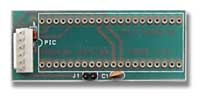
This carrier board provides a way for you to plug the PIC into the carrier board, which in turn plugs into the socket in your application. The white header is provided for easy attachment of the ICD cable. Jumper 1 controls whether the ICD is powering the PIC (J1 Jumpered), or if the target application is powering the PIC (J1 Open).
Note: You cannot just use the carrier board by itself. The PIC needs an external oscillator even during single-step debugging.
We are going to use the ICD with a P40 board.
Power -
There is a Jumper on the ICD itself labeled "INT / TAR". This selects whether the ICD is powered by the Target device or if it is powered Internally. If you are working on a P40 board that is being powered (or some other application that provides 5V), set the jumper to TAR and then attach the cable. The ICD should now be obtaining power through the 6-wire connection cable. No external supply is needed. We do not recommend this setup because the ICD cannot source enough current to provide the P40 board with enough current to light the LED and operate in Debug mode.
If you've got a 9-15V power supply handy (center positive), set this jumper to INT, plug the power supply directly onto the ICD, and the ICD will start flashing the D1 LED because it is fully powered, but has no MPLAB communications.
For this tutorial, we will assume that the Jumper is in the INT position, with a 12V 200mA power adapter powering the ICD and another 12V 200mA power adapter powering the P40 board directly. The green LED is blinking and the cable is attached from the ICD to the P40 board.
Software -
MPLAB version 6.30 does not support the original ICD. Microchip decided that the ICD2 was so great, that everyone would quite using their ICD - yippee! for software developers. You will need to download the last version of MPLAB that was compatible with the ICD, MPLAB v5.70 (if the link does not work, search the Microchip website for 'MPLAB v5.70'). Install MPLAB v5.70 and start 'er up.
New Project -
Under the 'Project' tab, select 'New Project'.
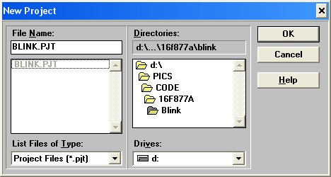
Select the directory in which the 'Blink.asm' code resides. Give the project a unique name. You can see we use 'Blink.pjt', but this is bad because we are going to have a large number of files all named the same thing. Click Ok.
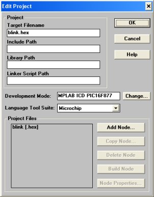
You should now be at the 'Edit Project' window. Click on the 'Change' button next to the Development Mode box.
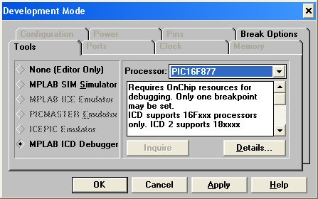
Here is where you tell MPLAB what you are planning on doing. Click on the diamond next to 'MPLAB ICD Debugger'. Select the correct processor. In our case, we are using the 16F877A, but the 'A' revision is not shown, the 16F877 will do. Click on Ok.
MPLAB will think for a moment while it attempts to establish communications with the ICD. The once blinking green LED on the ICD (labeled D1) should now show solid. If not, select the right comm port and click Reconnect.
Back in the 'Edit Project' window, click 'Add Node...'
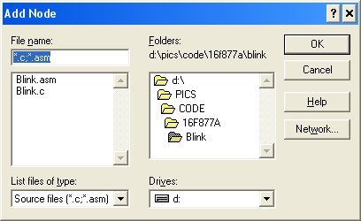
Select the 'Blink.asm' file and select Ok. Click Ok in the 'Edit Project' window.
Updating the ICD Firmware -
Because we are using the new and improved 'A' revision PIC (16F877A as opposed to 16F877) we will need to update the firmware on the ICD in order to communicate with these new parts.
First download the Update, unzip it, and store the 'ICD24001.OBJ' somewhere handy. Then click on the 'Options' button within the ICD control window. It should look like this:
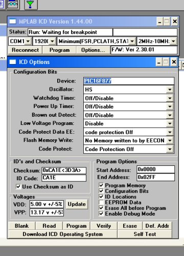
Click on the 'Download ICD Operating System'. It will ask for the update file you just unzipped. Point to the 'ICD24001.OBJ' file and click Ok. Now smoke 'em if you've got 'em... The download took us 3-4 minutes to complete. The slow serial connection has to load to 0x1DC0.
All right! All the hardware settings should be taken care of, time to get the Blink program onto the PIC!
Under the file menu, select 'Open' and open the Blink.asm file contained in the project directory.
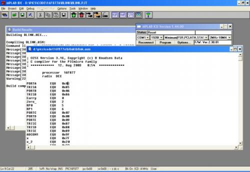
From here, click on the green funnel on the right end of the top menu. This is the compile button. MPLAB should successfully compile the 'blink.asm' file and create a 'blink.hex' file. Now we need to get the HEX file onto the PIC. Click on the 'Program' button. The ICD should do its thing and studiously program the '877A with the Blink program.
Note: This did not work the first time we tried it! After unplugging and re-plugging the cable, we got the HEX file loaded onto the PIC. But it still does not work. Why? Because you must do special things to your program to enable debugging. It would be best to read about this on the Microchip Website, but basically you need a NOP at program location 0x000 and reserve 6 bytes of RAM.
Using the CC5X compiler the following instruction enables ICD:
#define ICD_DEBUG
Something else to note with CC5X, this #define statement must come before the processor include file. The Blink.asm should already be ICD enabled. You should not have to worry about it.
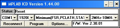
After clicking on the 'Program' button, the Status window should read 'Waiting for user command'. From here, you can click on the Green light in MPLAB to cause the program to execute fully - the LED on the P40 should blink. You may also use the foot step icon to step through the program a line at a time.
If MPLAB gives you an error "Error performing requested operation":
1) Double check all the connections.
2) Make sure the target board and the ICD are powered.
3) Click on Program again to re-load the target board with the HEX file.
4) If you are still running into problems, use our support forum: http://www.sparkfun.com/cgi-bin/phpbb/
From here you should have the ICD up and running. It can be difficult to setup, but the ICD is a powerful tool for catching the nastiest of code bugs. Happy stepping!
Comments 0 comments