
zagGrad
Member Since: November 5, 2007
Country: United States

Modkit - A new web-based graphical programming interface for Arduino looking for a little help
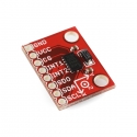
ITG-3200 Hookup Guide
October 22, 2013
Learn how to interact with the ITG-3200 Triple Axis Gyroscope.
-
The Arduino sketch is C++, but since it was written using the Arduino IDE there are some Arduino specific commands that are included by the IDE at compile time.
The processing sketch is written in...processing. Processing is it's own open source programming language. -

can you please confirm the alignment of the sensor axes?
The picture you've posted is correct.
I've been picking through Ryan Owen's DCM code on Git for a quadrocopter controller.
Answer #1: It's actually Jordi Munez's DCM code, based on the algorithm developed by Bill Permalani which I only ported to the ARM.
Answer #2: The coordinate system you describe is correct.
If you enable GPGSA and GPRMC, the GPRMC string consistently loses characters at the beginning of the string.
That's odd, I'll try to replicate it. Does the board exhibit this problem only with these 2 message types, or any message type?
Finally, I was wondering if Sparkfun might have any plans to improve firmware on the board itself?
Once the quadcopter is working I'll likely migrate some of the new filtering over to the Ultimate IMU repository. But I likely won't do too much more than that. I'd highly encourage you to fork the project and make any improvements you can think of! -

If you look in the actual library file (I think it's Si4735.cpp) you'll notice that the getFrequency function is...blank. It doesn't work yet. If someone can get some code working to return the frequency please post it and I'll add it to the library.
-

No, sorry, it's only compatible with the JPEG camera. The JPEG camera has a serial interface (Web Cams do not), and it outputs compressed jpeg files instead of raw image data (which is what a webcam would do).
As for adding a pir motion sensor, yes, it could be configured to work with the right pir motion sensor. -
Did you have the FTDI cable and the battery plugged in at the same time?
-
2 GB is fine. I'm pretty sure the maximum is 4GB.
Is your board getting hot, or just warm? You only have the battery plugged in right, not an FTDI cable too? It's OK if it gets warm. I use mine with the same battery and it's fine.
The LED won't come on unless there is a camera plugged in. This is because the board doesn't go into the READY state until it's communicated with the camera. You can test if the board is running the code by turning the board off, removing the microSD card, and turning the board back on. The LED should start blinking indicating the SD card couldn't initialize. It might take a second or two though. -
Please check to see if the trigger you wired up has somehow shorted the 5v and gnd rails that are located along the trigger inputs.
-
It'll break :( The code will get stuck in an infinite loop trying to name the new file. It would be very easy to modify to do your bidding though. Just change the '%03d' in the sprintf commands of the recordPicture function to '%04d' or however many numbers you want in there.
-
Maybe. The JPEG Trigger will accept voltages in the range of 1-5V. The 3.3V on the Trigger is regulated from the battery input, not the 5V rail (which is boosted from the battery input). So you may be able to plug the 5V rail from your system into the battery input of the JPEG Trigger; the only question is if the regulator on your system can handle the load.
-
The custom code was written with Arduino, and you can download the sketch above. If you only upload your custom code with Arduino, you can always revert back to the stock code by uploading this sketch.
If you don't like writing code in Arduino, you can also get the hex file for the stock sketch by downloading the code and compiling it with Arduino and then just grabbing the hex file out of the temp directory.


