ashcan
Member Since: October 9, 2008
Country: United States
-
Way, way cool. Now I have to go back and re-think my next order.
-

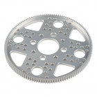
Improv simulation of the pick and place machine.
-

I told you to hold out for a REAL steak dinner.
-

God help us; we're in the hands of engineers.
-

I'm a little curious what's going on with this kit, the latest of which I just received today. I've used these kits in the past to teach kids soldering and basic electronics troubleshooting, so this isn't my first. One of the things I've found cool about this kit is that Sparkfun has promoted hacking into it and finding other creative uses for it. Big kudos for that in my book.
Towards that end, I was curious to which pins on the Mega328 I'd been given header access so I don't have to green-wire onto the chip to fully play with it. When I started looking at the new board, the first thing I noticed was that the number of pins down the sides of the microcontroller footprint wasn't the same; one side's got 13 pins and the other's got 14. Kinda weird, but maybe I'm going to learn something new today. In my time, I've never seen a 27-pin DIP package before. Consulting with Atmel's data sheet for this one, apparently they haven't either.
My next question would logically seem to ask how I get this 28-pin package soldered to a 27-pad footprint without cutting one of the pins off. No problem: somebody has already cut it off for me before the kit was packaged. Pin 14 is gone, hacked just about all the way back to the chip packaging so even green-wiring to it would take some extra doing. The missing pin is connected to PortB bit zero, as well as PCINT0, CLKO, and ICP1 functions. I hope I don't need them for any of my hacks.
OK - Let's go look at the board art and see if that can clarify what's going on. No joy there - The Eagle board art linked above to this product is significantly different than the board I received.
The old art shows the chip smack in the middle of the board, and pretty cleanly laid out. The only vias used were to get to the button pads. This was great to easily show a kid how their inputs and outputs connected to the chip.
The new board is another story. There are so many vias on this thing it looks like it was hit with bird shot. Try tracking uC pin 2; there are only two pads on this node, but it changes sides four, count 'em four, times before it gets to the pad on its other end on the FTDI header. In another life, I tried to have a blank board handy when debugging a populated board like this if I didn't have access to the art. At least the board photos on the web site are current, so I can use them the same way. Thankfully, this is still only a two-sided board. Even then, visually following these traces with a newbie is going to be a bear.
This board appears to be either the result of purely automated routing with no manual cleanup afterwards, or too much keep-out coverage to allow for simpler routing. I'd like to know why pin 14 is missing, though. My guess is that somebody defined the footprint with two single-row headers and botched the pin count instead of using a dip footprint. I can appreciate how much it sucks to have a large run of boards made and then find out they've got a problem. Been there, got the t-shirt.
This is where I RTFM. Thank you, Sparkfun for updating the booklet with the current images and information. A special note about pin 14 being missing would have helped.
A couple points:
The leds as delivered are not easily identified as to their colors. When I've put one of these kits together with a kid, I've brought along a current-limiting resistor (from my pile) and some alligator clips, hooked them up and watched them glow so we could tell what color each was and where to put it. It's not really important for the game, but it's nice to know when you hack into the code that #define LED_RED really means red. It's easy enough to change, anyhow, so it's not a biggie. I just like to be consistent between the schematic, the art, and the pretty pictures in the manual and on the box.
These buttons need debouncing, especially for a real-time game like this. The game, as delivered, easily thinks you've pressed a button more than once when you really didn't, which I've seen frustrate more than one kid. I modified the code for the surface-mount version to only return a value from the check_button function if it got the same value so many times, 'so-many' being defined by a constant. Around a thousand seemed to work well and agreed with my o-scope results, at least for the one unit I debugged. I can supply the code changes for anybody who wants it. I have not (yet) looked at the through-hole code, but I suspect the spirit of the code is about the same.
-
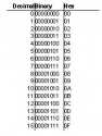
A four-bit field can be used to represent 16 different possible values. Values = 2^(storage bits).
-
There isn't as much bit-twiddling with the AS/400 as there is in embedded systems. My co-workers were in awe when I did an uppercase conversion by using %BITOR with a 0x80. It's a different world.
-
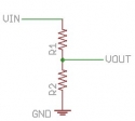
Voltage dividers are great, but they're a slippery slope if you don't have some idea of the input impedance being hooked to Vout. Fortunately, lots of things (like probably that a-d converter) have such a high input impedance they won't affect the result, but watch it.
-
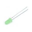
All well and good for this type of package. If I'm not sure (like the surface-mount LED's I've got that are about the size of a grain of coarse salt), I just power one up. If it doesn't work, flip it over. If it still doesn't, it never did. (My geek variation of the "If you love something" quote). Just watch your supply voltage/current.
-
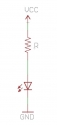
KVL says the voltages around a loop net to zero. If you use a positive voltage for supplies and negative voltages for loads (and call the voltage drop across the resistor Vr), then Vs-Vr-Vf = 0, or Vr=Vs-Vf. KCL says (paraphrasing) 'The current around a loop is the same', so the current flowing through the resistor will be the same as that flowing through the LED. Take the basic V=IR equation (E=IR if you're old enough) and rearrange it to be R=V/I. Note this equation is for the resistor only, which is Vr. Substituting the equation for Vr into this one yields R = (Vs-Vf)/I.
No public wish lists :(