- Home
- Product Categories
- WiFi
- SparkFun WiFly GSX Breakout

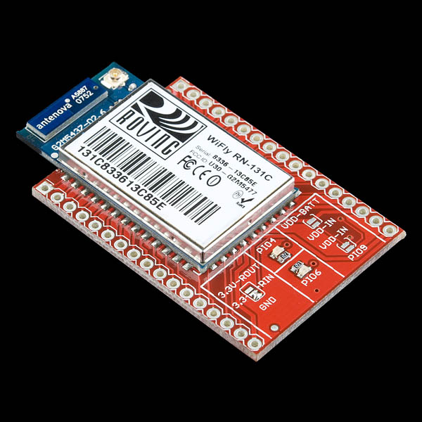
SparkFun WiFly GSX Breakout
We've revised the board by adding some LED indicators and also improving the overall performance of the board. This is a breakout board for the RN-131C WiFly GSX module, an ultra-low power 802.11b/g transceiver. This board breaks out all pins of the RN-131C to two 17-pin 0.1" pitch headers. Board comes fully assembled and tested as pictured.
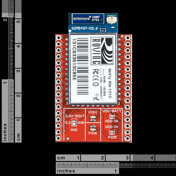
- 1.2x1.8" (headers are separated by 1.1")
SparkFun WiFly GSX Breakout Product Help and Resources
Core Skill: Soldering
This skill defines how difficult the soldering is on a particular product. It might be a couple simple solder joints, or require special reflow tools.
Skill Level: Noob - Some basic soldering is required, but it is limited to a just a few pins, basic through-hole soldering, and couple (if any) polarized components. A basic soldering iron is all you should need.
See all skill levels
Core Skill: Electrical Prototyping
If it requires power, you need to know how much, what all the pins do, and how to hook it up. You may need to reference datasheets, schematics, and know the ins and outs of electronics.
Skill Level: Rookie - You may be required to know a bit more about the component, such as orientation, or how to hook it up, in addition to power requirements. You will need to understand polarized components.
See all skill levels
Comments
Looking for answers to technical questions?
We welcome your comments and suggestions below. However, if you are looking for solutions to technical questions please see our Technical Assistance page.
Customer Reviews
3 out of 5
Based on 1 ratings:
1 of 1 found this helpful:
Good board but bad support & No working library
Once you navigate the difficulty getting this board working, it is stable and works well. The issue is for non-expert makers like myself that need good tutorials and examples to get comfortable with the board. Unfortunately, Sparkfun's "tutorial" is for a different board, the shield version and doesn't have any info about pinouts. Additionally, none of the Arduino libraries for this board actually work.
If you are a highly experienced programmer then you will enjoy this board's features and stability. but if you just want to get something that works without a lot of effort, I would recommend another wifi board with more support and tutorials.
I'm disappointed with the hookup guide since it goes to the WiFly shield instead of the the breakout board so there really isn't any guide to actually connecting this board to a Arduino... Also, the link for the wireless sensor project does not work,
is this comptible with Microchip PIC18F4550??? sorry to ask but I'm new to electronics ;P
it is compatiable with any microcontroller
Maybe a stupid question, do you need an antenna for this or has a gain chip on board? I can see the Antenna port just wondering if you actually need one
You don't need an antenna as there is already a trace antenna on board. You will just have increased range if you opt for the external antenna.
What are the differences between this one and the RN-XV???
I ordered 15 of these for a project I am working on and came across an issue. I have been through all teh docs but cannot seem to make it out. I am reading the sensor values with set q sensor 0x4 to read sense02. I also have it set for wake using set sys trigger 0x4. When my hardware sensor activates I have it take sense02 to GND. This wakes the device and it works as desired except for one issue. When my hardware sensor is not active the reading output says it is about 1V (4004 or 41FA etc).
On some of the devices I get a reading that is close to 0 (0002) for example when I apply the GND. On other devices it goes the other way (FF63) or something close to that. Ones that were reading high I did a factory RESET and reprogrammed the device and it corrected on others it did not. Any idea why the disparity? I have been scratching my head for 3 weeks!
How can I access the RSSI of the RN-131C? And is it possible to know it's link quality?
From the CMD prompt you can use show rssi. If you are using the UDP or TCP output using set opt format 0xff you can get the value from the url.rssi parameter.
The issue I had was that the output is in Two's Complement (http://en.wikipedia.org/wiki/Twos_Compliment). You will need to write code to translate it into readable rssi value.If you are not sure how to do that just search Google for the code you are writing in.
Hope that helps.
Im trying to power the device using a current-controlled power supply. The is problem is that it is not written in the manual how much normal current the device consumes. From my tests it seems it takes around 2 amp. Is this correct or Im I shorting something here???
Im trying to power the device using a current-controlled power supply. The is problem is that it is not written in the manual how much normal current the device consumes. From my tests it seems it takes around 2 amp. Is this correct or Im I shorting something here???
This was asked a few months ago but no answer was provided. Why would one purchase this over the xbee-form factor module (RN-XV: https://www.sparkfun.com/products/10822)? One answer is the RN-131 vs. RN-171, but other than that, are there other reasons? (just like the OP, i'm not asking to be an ass, just interested as the price differences are significant).
Save your money. If you want something that works out of the box, go elsewhere. This entire system is riddled with bugs and the documentation has never been updated. If you want UART only transmission, you might be satisfied. If you want speeds above 921 kbps you need to write your SDIO interface for SPI transmission to your micro controller. Roving networks have some example libraries but you need the RN171 development board, PIC processor or AMATEL processor, and even then you will need to write your own SDIO libary for it. When you decide its all too hard and revert back to the latests UART only firmware you will need to manually set each setting for ftp from scratch and use an update method not even listed in the documentation. If you do manage to get your firmware reverted, you will find your WiFly GSX wont save setting properly and eventually you'll just wish you'd purchased the GAINSPAN modules. Roving networks have horrible support. You will receive absolutely zilch from them and sparkfuns forums are dead and unmonitored by their staff.
Is this breakout board compatible with any arduino/compatible?
Has anyone got this working with a maple? I'm not having any luck.
Power: Supplying 3.3v regulated supply (VDD In, VDD Batt) and 3.3V RIN to ground (as per the documentation).
RX to TX, TX to RX
Simple serial setup and print('$$$') but no response. Tried jumping on GPIO 9 for a adhoc network however I don't know the mac address. Can somebody see something wrong?
I just got my board working with the teensy board regulated to 3.3V. The sketch is actually extremely simple but worked flawless. Maybe you forgot to sent your command as BYTES??? (I forgot that myself) You can check whether you really sent $$$ by connecting the Rx and Tx that are supposed to go to and from the WiFly. As a terminal program I used CoolTerm on the MAC in raw mode. You can send $$$ without sending a carriage return with that program.
/* UART Example, any character from the computer to the serial port, or USB serial is printed as a message to the Tx UART. The messages back from the WiFly are throughput from the WiFly (Teensy Rx UART) to the computer (Teensy USB).
This example code is in the public domain. */
// This line defines a "Uart" object to access the serial port HardwareSerial Uart = HardwareSerial();
void setup() { Serial.begin(9600); Uart.begin(9600); }
void loop() { int incomingByte;
}
Note that, although they advertise an SPI interface (instead of the UART interface), you have to request special SPI firmware from Roving Networks! They don't make this clear ANYWHERE. In fact, in the current version of the datasheet for this module, they actually removed any mention of the SPI pins. Weird.
I am trying to establish uart between arduino mega and gsx breakout board. I have simple voltage divider for tx/rx and is using Serial3 at 9600. It doesn't seem to be working and I am wondering if I have mistakenly burnt the board by applying 5V DC to either tx/rx. Is there a way to test this? In this case, UART wouldn't simply work?
After wiring this board twice, once with simple dangling leads (works perfectly) and then with headers plugged into a breadboard (doesn't work perfectly) I discovered that the board has to be raised about 4 mm in height above the breadboard. If this isn't done then the wifly cannot connect to a router, but strangely can still connect to a host in ad-hoc mode. Before coming to this conclusion I investigated different additional ground shields etc. Presumably this is the breadboard acting as a dielectric and affecting the wi-fi, or some other suitably waffly explanation!
Hope this helps!
Why would I buy this for $85 and not the RN-XV for $35, which is a perfectly fine wifi breakout module in its own right? What do I get for more than double the price? (Not intending to be mean, I'm genuinely curious)
For people who are intending to wire this up using the RX/TX connections of an Arduino,
After you read the datasheet, you'll quickly notice that the WiFly chip works with 3.3V all around and is really sensitive to anything higher.
It's not enough that you just power the chip using the 3.3V pin from the Arduino and a common ground. The RX/TX module works with 5V, just like anything else on the Arduino. (Quick explanation of UART and RS32 communication, it is basically a sequence of high and low signals, in Arduino UNO's case, from 0V to 5V).
There is a 3.3V Arduino Pro that you can use safely, but if you are intending on using any other ones, you need a level shifter like this one from Sparkfun, or you can build one yourself following this tutorial.
I burned my breakout board (it worked for a minute before I realized the 3.3V issue), so I just wanted to give everyone else a heads up before.
Good luck on your projects!
Mert
Overall, awesome product!
SparkFun,
I've spent over 2 days trying to get my WiFly GSX Breakout to work. I'm leaning toward the theory that I have a defective unit. I've tried each of these basic step by step guides:
http://arduinology.tumblr.com/WiFlyBuild
http://cairohackerspace.blogspot.com/2011/05/beginners-guide-to-connecting-and.html
It seems people generally get good success with the arduinology tutorial. The only difference in my setup is that i'm using a Mega instead of an Uno. The only output i ever get is:
Starting WiFly Tester.<br> Free memory:6667
Sticking some print statements in there i find that it ALWAYS hangs on WiFly.begin(); This has nothing to do with my wi-fi network or settings, it doesn't even get as far as initializing the module.
If anyone has any ideas, I'd be happy to hear them, otherwise, do you think that this might be a defective unit?
thanks
success! this person's wifly lib is working for me finally! https://github.com/jcrouchley/WiFly-Shield/tree/master/src/WiFly
the WiFly_WebServer and WiFly_WebClient examples worked pretty much right away. since i'm using a mega, i have Serial3 hooked up to the WiFly, and added these 2 lines in the beginning of setup()
Serial3.begin(9600);
WiFly.setUart(&Serial3);
hope this helps out others... this has been a very frustrating experience, but glad it's finally working.
This product has an unresolved issue with crashing and watchdog resets and is thus unreliable even in normal applications. See the RF/Wireless forum for more information.
http://forum.sparkfun.com/viewtopic.php?f=13&t=28926
Here's an example use of this module (actually the RN-134, which is simply Roving Networks' board around this very model) to connect a vacuum tube to the internet and display tweets:
https://trandi.wordpress.com/2011/09/26/vfd-clock-connects-to-the-internet/
Dan
Nice breakout board! We needed to run with a 5-volt Arduino system so we added a connector for 5-volt 'FTDI' cable and level-shifter for serial I/O. If there is any interest, you can see the modified schematic here
Bill Welch
I am trying to use two of these boards to make a 115200 baud wireless serial extension. I configure one end to make an adhoc network, and the other end to auto join to that network. It gets connected, but when it starts to stream bytes, it just chokes, and only sends partial data. I have tried loads of configuration settings, to no improvement. I contacted Roving Networks, and they advised added a soldered on wire between the radio can, and the ground point, which I did, but still it is not better. When I use the second module to 'scan', I get RSSI of -44, which is awesome, but still not getting a steady stream of data. My interrogation is to send a single 'm' character, every 0.5 seconds, and the receive side always sees that, but I only get small sections of the streaming response. Has anyone else every tried to use the modules in this way, and if so, what's the magic?
Is $35 more for the breakout board as compared to the bare chip really justified?
I didn't think so, especially given the good documentation, and large pads on the module. I bought the module by itself and soldered connections to it. Don't know if it works yet though, I haven't tested it.
I can't finf in the reference guide how to send a tcp message and how i will receive it :s can anyone help?
Hi, you have to configure the card as a client-server and open a connexion between the server and the card, you have to configure: 1)the server ip and port in the wifly module
2)When you want a connection, can be when the module wake up from first time or wake up from some sensor or timer configuration
3) You must have a server listen that port, I did a Java server and work great
To receive tcp message you have to open a connection with the card, you can make some test with "UTF-8 TeraTerm Pro" the card will send you back $$$ then you can do what you want open a UART connection, read a sensor, battery status, etc.
I hope this helps
I wish the shield library was compatible with this :-p
This may sound like a stupid question, but can wifly be used to access the Internet?
yes, You can download files from ftp servers, are some examples of how to read web pages in the datasheet
A nice and easy tutorial for wifly and arduino by the Egyptian (Cairo Hackerspace):
http://cairohackerspace.blogspot.com/
consider and think twice before buying the breakout version instead of the shield version.
Yes, this doesn't have the spi to uart.
We have 2 wifly gsx breakout modules. We want to connect computers screen to projector device wireless using these modules.
1-)We connected computers 15pin vga ports Red, Green,Blue,grounds, vertical and horizontal pins as GIO inputs of wifly. And this wifly has ADC. We expect to see these inputs as digital matrixes. But we couldn't find out a tera-terminal code for this?Do we need arduino or pic.?
2-)İf we solve first problem, we need to transform these inputs to our second wifly. How can we send?
3-) We need to convert second wiflys digital inputs into analog signals(because projection devices use analog inputs vga) but our module doesnt have DAC. How can we solve this?
There is also a second option that we use only one wifly module for this project. The computer sends the screen data to wifly that connected to projection device and it sends the analog signal to device. Bu we couldnt figure out if computer saves screen shots as digital matrixes and it can be change for various graphic cards. Can you advice smth for this
This will never work... just saying.
GPIO is digital, 15pin VGA ports are analog?
i just learned that the WiShield made by asynclabs will not be manufactured anymore.
So I am trying to migrate my work now by using the WiFly.
Unfortunately the WiFly shield is too big. But the WiFly GSX Breakout driver is not as comprehensive as the WiFly Arduino Library.
do you have any plan to make a smaller wifly shield?
thanks, stephan.
(shameless plug)
An Arduino library for driving the WiFly RN131 can be found at http://arduinology.tumblr.com/
Examples include a webserver and simple terminal.
Great chip, works fine.
Enjoy!
The reference guide talks about a keep out area on page 9.
"Keep out areas: There are two 1 mm round test pads on the bottom of the module. Avoid placing any exposed traces or vias in these areas".
The solder mask insulates the module from the ground plane on this PCB. If you ETCH your own PCB you will have to modify the board as indicated.
Can this be used with the 7.7" duck antenna sold here?
THe GSX has a U.FL connection for an external antenna. You could use a RP-SMA duck antenna with the adapter cable
I am sure that one works fine, however, the one Roving recommends is here: http://www.rovingnetworks.com/products/Cables and it is teh same price
I need to start saving some fancy shmancy euros and get this thing now it's in stock :)
Perfect! I was looking to make my own board since you were out of stock of the previous version.
This will be my freeday bonus :)