- Home
- Product Categories
- Level Shifters
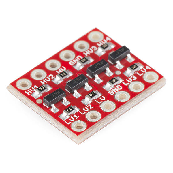
- SparkFun Logic Level Converter - Bi-Directional

SparkFun Logic Level Converter - Bi-Directional
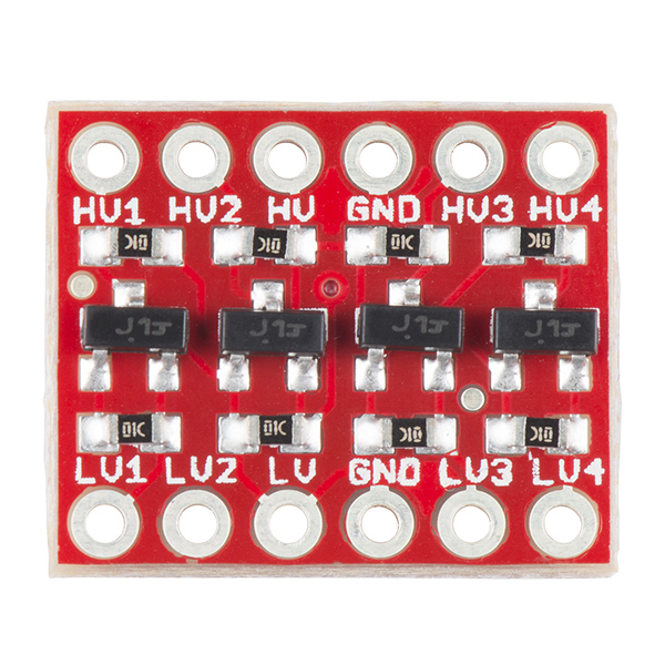
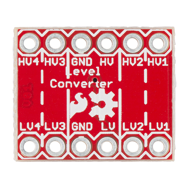
If you've ever tried to connect a 3.3V device to a 5V system, you know what a challenge it can be. The SparkFun bi-directional logic level converter is a small device that safely steps down 5V signals to 3.3V AND steps up 3.3V to 5V at the same time. This level converter also works with 2.8V and 1.8V devices. What really separates this Logic level converter from our previous versions is that you can successfully set your high and low voltages and step up and down between them safely on the same channel. Each level converter has the capability of converting 4 pins on the high side to 4 pins on the low side with two inputs and two outputs provided for each side.
The level converter is very easy to use. The board needs to be powered from the two voltages sources (high voltage and low voltage) that your system is using. High voltage (5V for example) to the 'HV' pin, low voltage (3.3V for example) to 'LV', and ground from the system to the 'GND' pin.
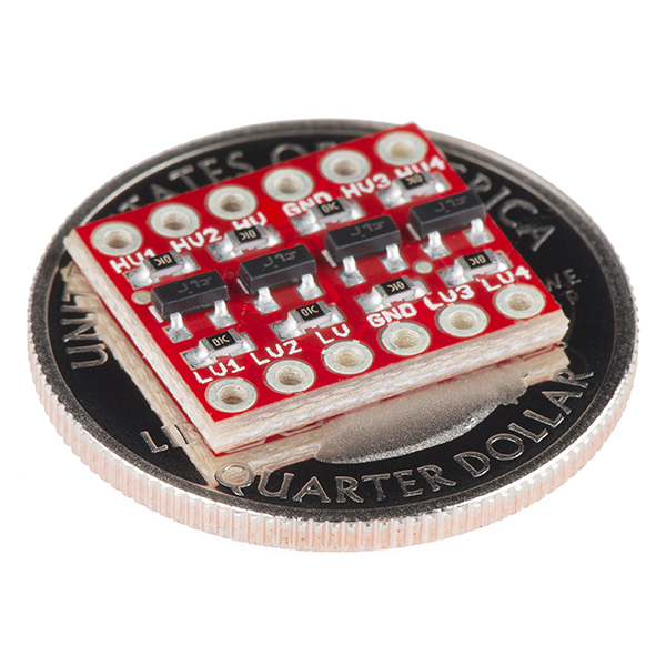
- 0.63 x 0.52" (16.05 x 13.33mm)
SparkFun Logic Level Converter - Bi-Directional Product Help and Resources
MicroView Digital Compass
October 24, 2016
Build a portable digital compass using the SparkFun MicroView and the MAG3110 Magnetometer Breakout.
Bi-Directional Logic Level Converter Hookup Guide
October 25, 2013
An overview of the Bi-Directional Logic Level Converter, and some example circuits to show how it works.
Highest Logic Level
We have tested this logic level converter more for 5V logic on the high side. Looking at the datasheet, the absolute maximum rating for the drain-source voltage is 50V with 0.22A continuous drain current. It should work for higher voltages based on this fact. We just have not stress tested this setup so we are not sure about how efficient it is when using 12V and 24V on the high side and 5V on the lower side.
Doing a quick test and measuring with a multimeter, the logic level converter was able to convert logic between 12V & 5V and vice versa. The logic level converter was also tested between 15V & 5V and 15V & 3.3V without any issues. There will probably be a slightly higher latency if there is a bigger voltage difference as the transistor switches between a logic HIGH or LOW.
Lowest Voltage Level
This logic level won’t work for anything lower than 1.8V. It won’t fully turn the MOSFET ON or OFF below that voltage level. We tried using it with 1V but the 5V logic side wouldn’t fully turn off.
If anyone requires a logic level conversion of around 1.0V, try looking at a dedicated converter. The PCA9306 [ https://www.sparkfun.com/products/11955 ] that was designed to convert voltage levels with I2C is able to reach about “1.0 V to 3.6 V and on the high side from 1.8 V to 5.5V.” There is also the TXB0104 [ https://www.sparkfun.com/products/11771 ] that can translate "1.2V to 3.6V on A Port and 1.65V to 5.5V on B Port (VCCA ≤ VCCB)".
Core Skill: Soldering
This skill defines how difficult the soldering is on a particular product. It might be a couple simple solder joints, or require special reflow tools.
Skill Level: Noob - Some basic soldering is required, but it is limited to a just a few pins, basic through-hole soldering, and couple (if any) polarized components. A basic soldering iron is all you should need.
See all skill levels
Core Skill: Programming
If a board needs code or communicates somehow, you're going to need to know how to program or interface with it. The programming skill is all about communication and code.
Skill Level: Rookie - You will need a better fundamental understand of what code is, and how it works. You will be using beginner-level software and development tools like Arduino. You will be dealing directly with code, but numerous examples and libraries are available. Sensors or shields will communicate with serial or TTL.
See all skill levels
Core Skill: Electrical Prototyping
If it requires power, you need to know how much, what all the pins do, and how to hook it up. You may need to reference datasheets, schematics, and know the ins and outs of electronics.
Skill Level: Rookie - You may be required to know a bit more about the component, such as orientation, or how to hook it up, in addition to power requirements. You will need to understand polarized components.
See all skill levels
Comments
Looking for answers to technical questions?
We welcome your comments and suggestions below. However, if you are looking for solutions to technical questions please see our Technical Assistance page.
Customer Reviews
4.6 out of 5
Based on 120 ratings:
6 of 6 found this helpful:
Great to talk to 3.3v device from 5V Arduino
Used this with an Arduino UNO to talk to a 3.3v ESP8266. Been working for a few hours and no magic smoke has left so I think that's a good sign.
1 of 1 found this helpful:
Meets the description
I am very pleased with the product and price. Just as described
3 of 3 found this helpful:
Works for me on LocoNet 3.3-12v
I am using a 3.3v micro-controller on my model railroad to interface DIY sensors and signals to Digitrax LocoNet runing at 12v. So far so good on a breadboard. Have yet to see what happens on a longer bus.
1 of 1 found this helpful:
Easy to use - works great
Quick soldering and easy to use. Straightforward and intuitive.
5 of 5 found this helpful:
Diversification test
While these were built to translate the voltage levels of TTL data streams, I found additional applications, such as MOSFET driver to isolate the sensitive IO ports on our Beaglebone Blacks, bring raw encoder outputs down from 5 to 3v3, isolate a high voltage SSR from the IO's and raise the input from 3v3 to 5v for more positive actuation. These have one more use for us, We originally tried to drive some high power MOSFETs with poor response, but after adding pull up resistors to the gates, and IO static with a pull down resistor set internally on the pin, we get very reliable control. In fact bandwidth of transmitted PWMs has almost tripled. This MOSFET controls large 12vdc coils for a hydraulic valve. Control response went from 97% - 99.9% range to 74% - 99.9%, giving tremendous improvement. Another feature is the bidirectional function of all ports. This allowed me to have two encoders on one chip. Two more permitted controlling 7 MOSFETS and one SSR with a tiny footprint of 1" x 2" x 3/4" including 33 wires for all three boards.
That tiny footprint saved me. Like I mentioned earlier, there are 9 TO 220 transistors, three with their own heatsinks, six more bonded to a common sink, 9 screw terminals for wiring the MOSFETs to their coil leads all crammed on a tiny business card sized computer development proto board. Similar to this: DEV-12774
If it could drive those big Mossy"s by itself I'd give it 5 Stars. Bryan
1 of 1 found this helpful:
easy and effective
Very simplistic and easy to use. I've used it on the Nokia Display and it works like a champ. For $3 you can't beat it and should buy a couple for your project prototypes.
2 of 2 found this helpful:
Works better than the competition!
I got a competitors level shifter and it was terrible. I had no idea such a simple thing could be executed so terribly. After figuring out what the problem was I ordered a handful of these Sparkfun boards and won't go back. Rock solid especially with I2C and SPI. The competitor's product seemed to generate a lot of AC for very little work. Some things are just better from Colorado I guess. Nothing against New York City but then again, I am a country boy...
1 of 1 found this helpful:
Works fine for 3.3v to 1.8v conversion
I used this converter with a BeagleBone Black to flash a SPI EEPROM which needed 1.8v.
Details and pictures on http://ao2.it/111
6 of 6 found this helpful:
Switching Speed too slow
I assume this logic level converter would work fine with i2c or some slower protocol, but, with high speed SPI the RC constant is far to slow with a 10k resistor.
1 of 1 found this helpful:
Perfect problem solver for voltage level shifting.
It was a perfect solution for me. I had been using the Raspberry Pi which uses 3.3V on its GPIO buss. Really useful now that I am using a break out board with a FT245. Inexpensive, small, easy to use.
1 of 1 found this helpful:
This thing converts logic levels, bi-directionally!
It turned my 5v signal into a 3v signal! And vice versa!
2 of 2 found this helpful:
Perfect
Long delivery time but perfect.
8 of 8 found this helpful:
There is only one real limitation with these. namely that they rely on both devices to be "Open collector". which means the devices need to be able to actively pull the signal down to ground to work. not all devices do that so it is best to make sure they do this. if your device works by actively pulling the signal up and not down this won't work.
However when used appropriately these are pretty fantastic. great for communication busses like I2C,1-wire and such.
1 of 1 found this helpful:
Came fast, worked as expected. Data sheet easily found on the website.
1 of 1 found this helpful:
It works....
....because it was designed properly. Thanx.
1 of 1 found this helpful:
Robust board, easy to use
Easy to use board. Just set high and low reference voltage and instant bidirectional communications between board with different source voltages.
1 of 1 found this helpful:
Exactly what I wanted!
this was a simple board but suited perfectly for level shifting in breadboard prototypes!
1 of 1 found this helpful:
Driving ST Micro SWIM Lines Down an 8 foot Cable
ST Micro SWIM (Single Wire Interface Module) is not meant to go very far . . . SparkFun Logic Level Converter - Bi-Directional did the trick. I did have to decrease the pull up resistors on the HV side to about 1K to get enough "voom" to shape up the edges but it worked which is saving me from some serious headaches.
3 of 3 found this helpful:
WS2811 LEDs
I managed to get this working with a Teensy 3.1 and the OctoWS2811 library using 3.3v as the input voltage and 12v as the output to control a string of LEDs. This was straightforward once I realized that the Teensy's TTL output was at 3.3v and not the 5v I was using as the Teensy VIN.
I've only tested a single strand of lights with this, however, so YMMV with different variations.
2 of 2 found this helpful:
Works Great!
I use it to convert logic levels from my Arduino and ESP8266. Haven't had any issues so far.
4 of 4 found this helpful:
Great for I2C, UART, less great for SPI
I used this with my dev kit which has a logical voltage of 1V8 to drive several 5V and 3V3 devices. The 3V3 I2C LEDs worked like a charm and UART seems to work fine, but I had a 5V SPI device going at 1MHz that was not responding correctly. Scoping it out showed that the clock signal was only going to about 2.3V at its height, not enough to trigger a rising edge. Still a great little device though, and I can reuse for other prototyping.
1 of 1 found this helpful:
Good,small package.
I use these all the time in designs that require tight packaging. This works well for my needs.
1 of 1 found this helpful:
Best size, 4lines. Good price. Would be usefull single an bi/lines modules too
2 of 2 found this helpful:
Did just what I needed.
I needed to get my Arduino (5V) talking to a Gumstix (1.8V) module via Serial/UART. This level converter does the trick.
2 of 2 found this helpful:
Excellent level shifter
small footprint, easy to use, reliable. I use it to interface 3.3 volt MCUs to 5 volt devices
4 of 4 found this helpful:
Doing the job perfectly for my ESP8266 module.
When it's critical for your component to have those back and forth signals pulled down to 3.3v from the standard UNO/MEGA board 5v signal, this is perfect. Thanks, Sparkfun Team! (NOTE: I should have ordered two though, one for the breadboard prototype, and one for the final project assembly.)
1 of 1 found this helpful:
Hookup guide could explain much more.
1 of 1 found this helpful:
Worked great for Noctua 5V PWM Fan
I used this to allow an ESP32 (3.3V) to control a Noctua 5V PWM fan and it worked great, even for the high 25KHz PWM frequency.
I only needed one channel (or lane, not sure what to call it) however so I wish there was a smaller board with one or two channels which would have saved me some space in my project box
2 of 2 found this helpful:
Works fine, nice design, priced right.
Small systems today often incorporate a mix of peripheral sensors or actuators which operate on different logic levels. Especially 3.3 and 5 volt. It's easy enough to lash up your own bi-directional converter with a MOSFET and a couple resistors but at the $2.95 price for this 4-channel device, why bother! An easy to use product and reasonably priced.
10 of 12 found this helpful:
Doesn't work with WS2812 LED control IC
I needed something to translate the 3.3V GPIO control signals coming out of my Raspberry Pi to 5V in order to control a WS2812 LED controller (specifically https://www.sparkfun.com/products/12877). The control signals for the WS2812 run at 800kHz, with an allowable delay time of +/-150ns.
The data sheet for this converter says that the turn-on time, rise time, and delay time are all in the sub 40ns range--so it should work fine, right?
Wrong. The WS2812 glitches like crazy when I try to control it through this logic level converter, so for my purposes, this part is useless. On the plus side, it was only $3, so it's not like I wasted much money.
3 of 4 found this helpful:
Does its job
I got this to connect my Edison (1.8V I/O) to a Sparkfun LSM9DS0 breakout (3.3V I/O) using i2c. It's working perfectly, so far.
My only complaint is that I wouldn't have needed this at all if the LSM9DS0 breakout had brought out the Vdd_IO pin rather than tying it to Vdd.
2 of 3 found this helpful:
Works well
Used to talk between my 5V arduino and a 12V IC. Needed to slow down the arduino SPI bus otherwise the converter would not be able to send an adequate signal. Once the bus was slowed down however, converter worked well.
Needed for Arduino and BME280
Used this with an Arduino communicating with two BME280's over I2C. Since they are strictly 3.3V devices, the bi-directional logic level convertor is required. It works great and is very small allowing it to be incorporated without taking up much space.
Great Product
I used this in a project to interface a FPGA and a SNES controller. Works flawlessly.
Excellent!
Works exactly as stated.
Works just as expected
Makes connecting to 3.3V from arduino extremely easy
My enduser says, "They work!"
Though short on words, my enduser is a mechanical engineer who's long on usefulness. His succinct summary of this product is, "They work!"
Exactly what it says on the tin
It was easy to solder, and worked exactly as needed for the project I was working on. The only thing missing is if it could somehow only require one reference voltage as input, but that would likely increase board complexity compared to the simple workhorse we have here.
Easy and Straightforward
Purchased this level shifter for a 5V to 3V I2C connection and it worked out of the box without a hitch. I didn't do too much digging but I believe the onboard resistors worked nicely for the I2C pullups. I also thought the price was very good considering.
Works great
Performed as expected, got my project back on track, thanks!
Works great!!!
In setting up a Parallax Propeller micro-controller(3.3v) to work with a Matrix Orbital LK204-25 LCD (5v) using a I2C interface, I needed a bi-directional logic-level converter. This module/board worked out great. I needed only two channels for the SDA & SCL I/O lines, but having an additional two channels on this module/board will be useful for future expansion.
Works great!
I realized that I need 6-bit converter. So I've re-designed and laid out 6-bit converter with BSS138 MOSFET. Now waiting for my board to arrive from being fabricated. That way, this board will make a nice interface board for the SparkFun Micro OLED Breakout (LCD-13003). Less wiring!
Used it to connect a 5V Photo-Interrupter to a 3.3V ESP8266
It took a bit of convincing before I believed I knew how to hook it up. Nothing could be easier: connect the two power supplies to the HV and LV inputs, connect the grounds, then connect your high level and low level signals and Voila!
I bought the bi-directional part so I could use it for ESP8266 outputs as well as inputs.
Worked for me right out of the box. I expect I'll be using more of these as I connect 5V parts to my 3.3V ESP8266 Thing boards.
Excellent product
The product does exactly what it claims, i.e. convert from 5v to 3.3v. I'm using three on a cape I've designed for the Beaglebone Black which requires the 3.3v signals. My only complaint is that I'm using it with a through hole circuit board so leads would be nice instead of having to do surface mount soldering.
Great
Works fine. No problems.
Great little interfaces
If you're working between 3.3v and 5v you need this little baby. Makes the job of converting logic level easy.
The Price is Right
Caution, object in the picture is much smaller that it appears. Other than that, it works as advertise at a price that is right.
It works!
Worked the first time for me. I don't really know much about electronics but I wired it up and it worked, so there you have it.
Perfect in Performance and Simplicity
I wish all components were like this one! I soldered the header pins and then connected 5V to one of the HV pins and checked the voltage on the corresponding LV pin. It was spot on 3.3V. Not much more than you can say other than the price was great too! The folks and products at Sparkfun are great!
The Four independent channels make it universal ! Wish I had it a long time ago..
Many times I had to add resistors or transistors / resistors to the breadboard circuit before I had to layout the prototype I was working on that took way too much time. Well, here it is already to put to work for your without any lost time. The Four Independent channels are easy to hook-up with this breadboard ready module. Easy hook up to 5 volts to the HV input, 3.3 volts to the LV input. Then hook your LV device to the LV terminal and your 5 volt device to the HV terminal. That is all there is to it !
Worked as stated
Used 3 to bump up the signal lines from my smoothie board to some external drivers. Haven't seen any issues yet. Hope to have them under full load soon.
It works perfectly, easy to use, great operation.
Great interface for 3.3V to 5V translator. No issue using it. 3.3V cpu able to interface with a 5V part. I'm glad I found this device.
works as it describes
The board works good as it describes. I use it for the UART communication between adrduino mkr and other 5 V boards. Hope the board comes with soldered connectors.
Nice little converter board
I am glad that it can handle many different conversion voltages. I want to convert signals from 3.3V to 16V, and this does that easily. I have managed to toast a few channels during testing, but I only need 2 channels and there are 4.
Cheap and convenient
Works exactly as advertised. Fast and convenient for prototyping. Very satisfied.
Great !
Thanks for the prompt delivery :-)
Work great and got here fast!
These are just what I needed for my project, the price was right, and they got here fast! That is the way all the Sparkfun devices I have ever bought have been.
Solved the problem
Worked as advertised and simplified project!
Great!
Simple, easy to use. 5 stars for the Philips application note.
Works without even thinking about it.
Board is labelled well and I plugged it in and started using it. Didn't even need to look at instructions or datasheets
5 V to 3.6 V Logic Level Converter
Worked exactly as advertised to link 5 V 328P and 1284P processors to the 3.6V Qwiic SEN-15177 / Vishay VCNL4040 Proximity Sensor which also worked as advertised.
Does what it says on the tin.
Level shifting a 3V3 uC controlling a 1V8 I2C barometric pressure sensor (TDK InvenSense).
Uhg... I wish I could add a picture from my scope.
I bought these, and a different product (based on a TXS0108E), so that I could compare the two and see which one had the best response signal and least delay. I like that it was in a small package.
What I saw on my scope is that these barely raised the voltage on the high side. For example, the SparkFun converter had a top voltage of 3.33 on the 5V side, while the TXS0108e had a top voltage of 4.32 on the 5V side. When converting from 5V to 3V this product performed equal to the TXS0108E.
I think you might have these connected wrong. Please contact our technical assistance team for help in resolving your issue with this board.
good quad level converters
I really like this board because: - it is well laid out and well labeled - 4 converters on a very small board (~ 1 cm square) - reasonable price - it works.
missing pins
board usually came with pins . my package dose not includes any pin .
I'm sorry, but none of our boards come with headers. You should receive exactly what's pictured on the product page.
The logic level converters are great
Its a wonderful device, thank you
Converts Levels
Got a 5V arduino but a 3.3V sensor? Have a soldering setup? This little guy'll do ya!
Works better than 74HC4050D
In our experience it works better than 74HC4050D equivalent circuit. We use the board as-is in our own designs for our RFM69 and LoRa shields.
Works well
Does job for interfacing I2C, No crosstalk as with China ic devices.
worked perfect for my 3.3 v out put I was looking for.
Novice beware.
If you're a noob at soldering like I am, trying to get header pins on this thing was a nightmare.
Works Perfectly!
I’m using the Logic Level Converter to drive the 3.3v Qwiic Relay using a 5v Arduino Pro Mini. It works perfectly and the small footprint is just what I need.
So far so good
Very good instructions on the web site for use.
Easier than discrete parts
Needed this function in a project and had thought about just wiring up the required MOSFETs and resistors myself, but at this price and the ease of dropping it into my design outweighed trying to find board space and routing the connections myself. Small footprint was less than the discrete components would have used, so very happy with the solution.
Great little board!
This level shifter does exactly what it should do and what Sparkfun says it will do, shift 3.3 volt logic levels up to 5.0 volt levels and the other way around too. I have looked at the signals on a digital oscilloscope with the board connected to i2c bus signals and find them to be clean and exactly correct for each voltage level. It's very easy to figure out how to connect it to your circuit: HV (5.0 volt) and GND pins on one side of the board with all the rest of the HV signal pins, LV (3.3 volt) and GND pins on the other side of the board with all the rest of the LV signal pins. This is a good little board to have around!
Using a bunch of them for bus conversion between 3.3 and 5v
Only suggestion I have would be to add bypass caps for both supplies.
level shifter worked with cheap hoverboard motor driver
The project i am working includes connecting the various sensor and control signals between a 5 volt - does not work with the other digital level shifter, to a pi pico. These boards do the job.
The TXB04 type just didn't work reliably.
Note that you can see the diode bias the signal 0.8 volts with these boards, but that doesn't seem to matter to the processor (3 volt on that side).
Works well!
I needed a level shifter to go between a 5v Arduino Micro and a 3.3V Seeduino XIAO. I didn't want to have to build a discrete component version, so I was lucky to find this product first.
Must Have, Very Easy to Use
Most of my Arduino type boards are 5V although many do have 3.3V available. Nevertheless, with this converter it is easy to wire up 3.3V devices to 5V.
There is a picture posted in Forums under Environmental Sensors under RobRal
Haven't used them yet
No time to spare
The problem was somewhere else
Maybe I did something wrong, but mine sent the HV (5V) down the LV line and killed my NANO 33 BLE. I double-checked everything and installed the backup NANO and another Converted ... poof, same thing. I'm waiting for an overnight delivery of another NANO, but I threw out the other Converters I bought. Correction: The Eplzon PC Board had the positive and negative bus tie point mislabeled. Instead of tying the two common buses together, I tied the 5 and 3.3 volt buses together. This is what caused the Arduino destruction and the resulting foul language.
Great RPi 3.3v to 1.8v level shifter
Only need a few hundred microamps of drive from the 1.8v side and this worked well for that. I used this to program an MX25U6435F QSPI device (as SPI).
Works well with I²C
Here's are some demo videos of using this product with I²C
https://youtu.be/LwOlzQDhr-A https://youtu.be/dP9_afbdtBU
A must have.
I bought 4 so that I have plenty for future projects. I constantly run into the need to talk between 1 voltage system and another. This made it possible to use a wider variety of chips without consulting logic voltage before purchase. Great board to have in my candybox.
Works as expected. Quick and easy!
Works as expected. Quick and easy! Soldered the headers for prototyping and the thing can plug into a breadboard just fine no matter which side of the PCB you solder your pin headers. Pretty cool!
Flawless!!!
Used this board on 2 different projects. Absolutely no hitches or problems!!! Highly recommend it.
Indispensable when interfacing I2C 5V with 3V3
I've used this to connect a 3V3 I2C device to a 5V Arduino board. Have also used it to connect 5V I2C devices to 3V3 Teensy boards. Always works perfectly.
It works
As advertised. No Complaints.
Good Level converter
Excellent product
Level converter
Works fine, as advertised and as expected. I don't expect any problems. I would recommend this product from sparkfun.
Goodie
This is nerve-saver, no need to ''play'' with resistors, but resistors have benefit of taking small space if only 1 or 2 lines are needed.
it is perfect for my application
My PCBs that I create are very flexable
does exactly what it's supposed to do
bbb <- serial -> arduino uno. i got my bbb and arduino uno talking to each other using serial. thanks!
Works as advertised
Works great for level shifting (UART in my case). Well thought out pin layout for breadboarding. Also, having the schematic available is very handy.
Simple and effective
This essential building block is achieved with just one transistor and two resistors (with the help of the internal diode). It simply works very well with a small footprint.
Easy to hook up and it works!
This is a great converter to go from 3.3v to 5v. Makes it very easy to connect ESP8266 WiFi board to a 5v Arduino Uno.
Perfect and minimizes circuit components
WEoks perfectly, and does not take up unnecessary wiring space on your circuit board.
Great Device, works as advertised
Bought 2 for use in a dual SPI sensor project, Both level shifters worked just as advertised. Cheap insurance as a go-between on arduino projects.
Perfect for devices which don't play nice
I had a Kinetis FRDM-K64F that spoke 3v3 I2C, and an Adafruit LCD Backpack that only spoke 5v I2C, and couldn't trigger off 3v3. This converter was exactly the thing to get the two talking.
Great product.
I only wished this product came in an eight channel version.
Tiny, inexpensive, does what it should
It's a quality product. I used it to process signals from rasp pi 3. It works perfectly.
Immensely practical when level conversion is needed
Very easy to use: just solder in the headers, hook up the two levels (e.g. 5V and 3.3V) to the inputs/outputs from a 3.3V device (e.g. an I2C device) and you are done in five minuted compared to researching and building it yourself.
Worked as advertised ..
Connected it to the RFM69 using a 5V Arduino UNO and it worked perfectly
Essential gear
In this world of 3.3v and 5V chips, this is the easiest way to get between them, I'd love an 8 bit version at some point. Pretty simple to use, and if you aren't driving LEDs or counting on tri-state logic it works well. I found it useful to talk to 5V SPI interfaces from a 3.3V microprocessor.
Worked great for my project
I used the bi-directional board to connect a small OLED screen (https://www.sparkfun.com/products/13003) to a RedBoard. The screen required 3.3 V signal from a variety of pins. Using this bi-directional board was very simple to make the necessary connections between pins on the redboard and OLED board.
Works just as advertised, quick shipping, good value
Works just as advertised, quick shipping, good value.
The board is a high quality PCB, and the workmanship is great.
No problems here.
Works Perfectly
I used it to level shift signals between a PSOC5 and a Playstation 2 controller. Worked like a charm.
Useful product . Is perfect for a 24 volt to 5 volt application.
worth mentioning that the GND and VDD are the wrong way around on the hookup guide, compared to the PCB (mine at least). cheers, otherwise works fine for i2c at least.
Will this work with the SparkFun ToF Range Finder Breakout - VL6180 which requires 2.8V logic?
Do I just put 3.3V on the High Side?
Would this work for a 3.3V micro to communicate with a 5V onewire (1wire) device in full powered or parasite power mode? What I'm thinking is a SparkFun Pro RF LoRa running on battery/solar reading up to 40 onewire ds18b20 sensors spread out on 4 inputs. In my experience that number of sensors works best on full powered mode, 5V but unfortunately the commercial sensor strings are setup for parasite power mode so I'm unsure if this level shifter would provide enough pullup to charge the sensors' internal parasite power capacitors. I realize on battery power they will only get vBatt but that's at least a little better then 3.3V.
Hi there, it sounds like you are looking for technical assistance. Please use the link in the banner above, to get started with posting a topic in our forums. However, you might need to rely on community feedback as this sounds outside the scope of our support team.
Not recommended for digital led strip. However, at the moment I still use it because of the low price but I reduce the frequency to 500KHz (instead of 12MHz when using pjrc prop shield). To be more precise, I need 3.3V to 5V conversion for an APA102 leds strip. The scope shows the period of 2us with T_ON of 1.3us. Signal reaches 4V with difficulty on the T_ON time. Sparkfun should update the description with warning for that.
Hello, I made an account just to ask this question, as it has been driving me crazy. For some reason, when I have 3.3V on the LV and 5V (actually around 5.5V) on the HV, the signals coming out of the HV end are all around 2.6V. Does anyone have some suggestions to fix this? Thank you!
a silly question. May I use it with 3.3V in both sides in my hand made shield if I connect it a 3.3V microcontroller? I meant to have the option of connection a 3.3V or a 5V microcontroller.
or is there any other option to achieve that?
Could it handle 24V to 5V conversion?
Nope
Can anyone comment to how this responds to V-Low = V-High? I would like to be able to use a switch to toggle V-Low to either 3V or 5V. AKA. Sometimes I need level conversion, sometimes I don't. Thanks!
Any chance of getting this part into the Fritzing parts list for sparkfun? The unidirectional level converter is in there but the pins do not match.
What is the ground pin used for? In the schematic it appears to be not connected but not connecting them in my current setup gives strange results.
Looking closely at the picture it appears the grounds are tied together and form a ground plane on the back side of the the board. So, they provide a common ground for whatever two circuits or boards you are translating levels between. Not hooking them up would cause the signals to float and give unreliable results.
Great board for the project I am currently working on which needs level shifting on the I2C BUS.
Have you thought of making a shield to level shift between a 3.3V Arduino/shield and a 5V shield or the other way around. Then one simply uses the shield to make other shields compatible with shields of another voltage.
One consideration that must be taken into account if this level shifter is used for i2C, which requires pullup resisters for the BUS. And that is the resulting pullup resistance in the I2C BUS.
@Rob36 I too have been trying to use this as a level shifter for my 5v i2c sensor. But haven't been able to make it work. Should I keep the pullup resistors or get rid of them? When my sensor's connected to the arduino it requires a 4.4K pullup to function normally. I am trying to connect the sensor with electric imp.
Very cool board, but I'm not sure that this will work reliably with 1.8V devices. From the referenced Philips application note the low voltage should be at least 1V higher than the threshold Vgs value of the MOSFET. The BSS138 has a maximum Vgs threshold of 1.5V (1.3V typical), so this circuit should work down to 2.3V, but 2.5V is safer. At 1.8V there may still be enough juice to turn the MOSFET on, but I'm not sure I would trust the results.
Is this functionally equivelent to the PCA9306?
I've gone over what documentation I can find on both pages and can't see that there is a difference, between cost, IO's, and labelling. And would love to learn if/what the differences are.
Thanks
Seems to be equivalent to Adafruit's 4-channel I2C-safe Bi-directional Logic Level Converter which is $1 more expensive
Will this breakout board work if LV == HV? I'm wondering if this would be suitable for an I2C-based shield (3.3V) that might be connected to either an Uno (5V) or a Due (3.3V).
Can we use this board in between my MCU and GSM modem to shift UART voltage level? My baudrate is 115200.
will this work to convert the electric imp's 3.3v into 5v to power and 5v device IF i dont have a previously existing 5v power source?
Can this handle tristate pins? i.e. if one side is not connected, will the other side also appear to be unconnected?
What is the introduced delay? The data sheet says it's 5ns - is this all there is to know?
Does it work for I2C?
After taking a look into the Hookup-Guide, it turns out: Yes. SPI, UART, I2C - Compatible
Hi. I need to convert between logic levels 3.3 & 5V. The thing is both devices have 5V power rails so I don't have a 3.3 reference. Will this or the 11771 work?
What is the cut-on voltage for the BOB on the HV side if HV is set to 5v? I ask because sometimes the device I'm connecting to the HV side has 5v signals, and sometimes it has 3.3v signals (with HV set to 5v in both cases). It seems to work, but I wonder if I'm on the hairy edge. If cut-on is 2-2.5v then I think I'm ok, if it's around 3v then it might miss sometimes.
Could I also use this to convert 5v signals to 1.8v signals for example??
What is the bandwidth of the converter? I am using it to convert a 20 kHz PWM signal from 3.3 V to 5 V. On oscilloscope, from a rising edge input signal, the output signal starts with a first-order response from 3.3 to 5 V, reaching 4.98 V after 2 µs, in other words, a first-order response with a time constant of 1.1 µs (See an oscilloscope screenshot at http://i57.tinypic.com/20k6nsw.png). I could not find similar numbers in the BSS138 datasheet but I am not an electronic engineer. Is that first-order time constant correct?
Anybody know the actual pad dimensions for us non-Eagle users? I don't have it yet but want to begin laying out a board, and I would rather not guess. Thanks.
13 x 15 mm
This looks like it will work in a 24 volt to 5 volt application. Is that correct?
THanks
Hey I need Help,
As per above Product, i buyed the 8 Channel Level Shifter.
Is it necessary to connect both the voltages 3.3 and 5v also.....?????? Hey I need Help please Comment fast
This is a great little board -- it fits right in where the older versions of the SFE logic level converters went and works better! So glad that Sparkfun redesigned the board for full flexibility on all channels! Thanks sparkfun -- using these things all over the place in my mixed voltage digital projects!
Can this be used for 12volt to 5 volt level conversion?
Hi,
Silly question maybe...(excuse the non-electronics person...) but the tech document attached - AN97055 suggests that you ought to be able to approach 10ns switch on/off times... I was just wondering whether it was realistically possible to do this with this board - or whether you would need to play more with the pull up resistors?
I am trying to use this with my electric imp as an I2C level shifter for my sensor which requires 5V input. At 5V with an arduino, it needed a pull up resistor of 4.7K. But I haven't been able to make it work with the electric imp. What do you propose me to do about the pull up resistor while connecting with the electric imp!
Would this work to connect a 12V RS232 with 3.3V logic? What is the highest voltage it can support? Thanks,
Michele
I bought a couple of these to convert teensy 3.1's 3.3v data signal up to 5v to communicate more effectively with adafruit's neoPixels.
I've read a lot about people using the 74HCT245 but should this perform a similar function?
So far I'm having some intermittent problems that I'm not yet sure are related to this, or my code.
I have just proven to myself that this board DOES NOT work for interfacing a Teensy 3.0/3.1 to WS2812B LEDs (aka Neopixels.) Glitches like a bastard.
Do NOT waste your time with this, use the 74HCT245 like everyone who's actually tried it recommends.
(That said I'm having success just plugging the DIN on the strips directly to a Teensy's digital pin.)
What would be great is if this breakout board was expanded to also include regulators for 5V and 3.3V for example. Maybe with jumpers to HV and LV.
This way all the regulation (signal and current) are combined in one pack.
I'll probably hack something like this together myself. (maybe first ordered custom pcb :))
@GMAN - that is the MAX Vgs
What you want is the MIN Vgs which is 0.8V With the 1V suggested margin that goes up to 1.8V, and you should have no issues switching 1.8V devices.
I use this board with the TTL serial coming out of a Parrot ARDrone at 1.8V and have had no issues, switching at 115200 baud.
Cheers.
will this work with analog signals
Not at all.
Excellent and useful product, but I require more than 4 conversion lines. Although I can use 2 of these, I still prefer more than 4 channels on a single board, like the following very similar product:
http://ezsbc.com/index.php/products/ls1.html#.UnEWkHBRrKA
Hope to make this work for 3V to 15V. Hey, love the Skills icons, but they don't show up for everything. Will you be retrofitting them to current products eventually, or only tacking them to new products (starting recently, I assume)? Brief mention here.
Awesome. finally you guys made a quad bidirectional version of the logic converter circuit (it was quite requested i do believe).
Do you have a good recommendation for a converter that works with 12V to 5V and vice versa?
This board will handle 12V-to-5V or 5V-to-12V conversion. Just make sure the HV and LV are connected properly and you'll be good to go.
This board will also work great for converting 3.3V or 5V PWM to 10V PWM for use with things like the the dimming control on MeanWell LED power supplies.
I assume that would that include the Mean Well ELN-60-48P dimmable driver? It requires a 10v PWM. And if so, do I just connect an external 10V DC supply to the HV, and the mean well driver to HV1?