- Home
- Product Categories
- Weather
- Humidity and Temperature Sensor - DHT20

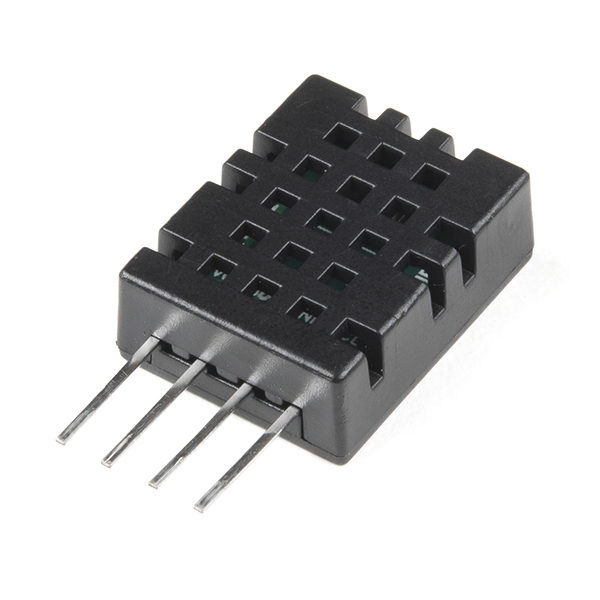
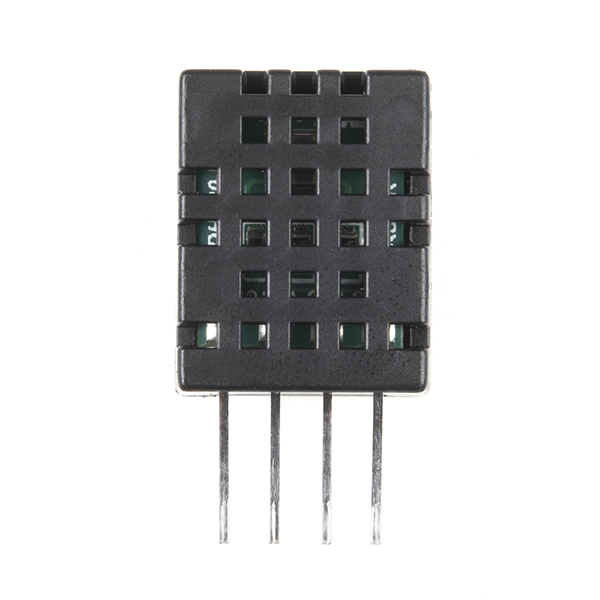
Humidity and Temperature Sensor - DHT20
The DHT20 is a low cost humidity and temperature sensor with a I2C digital output protocol. It can be applied to HVAC, dehumidifier, automatic control, data loggers, weather stations, and many other projects. The sensor is calibrated and doesn't require extra components so you can get right to measuring relative humidity and temperature.
- Supply Voltage: 2.2-5.5V
- Communication: Standard I2C Protocol
- Humidity from 0-100% RH
- Typical accuracy: RH: ±3%, T: ±0.5℃
- -40 - 80 degrees C temperature range
Humidity and Temperature Sensor - DHT20 Product Help and Resources
Core Skill: Programming
If a board needs code or communicates somehow, you're going to need to know how to program or interface with it. The programming skill is all about communication and code.
Skill Level: Rookie - You will need a better fundamental understand of what code is, and how it works. You will be using beginner-level software and development tools like Arduino. You will be dealing directly with code, but numerous examples and libraries are available. Sensors or shields will communicate with serial or TTL.
See all skill levels
Core Skill: Electrical Prototyping
If it requires power, you need to know how much, what all the pins do, and how to hook it up. You may need to reference datasheets, schematics, and know the ins and outs of electronics.
Skill Level: Competent - You will be required to reference a datasheet or schematic to know how to use a component. Your knowledge of a datasheet will only require basic features like power requirements, pinouts, or communications type. Also, you may need a power supply that?s greater than 12V or more than 1A worth of current.
See all skill levels
Comments
Looking for answers to technical questions?
We welcome your comments and suggestions below. However, if you are looking for solutions to technical questions please see our Technical Assistance page.
Customer Reviews
3.5 out of 5
Based on 4 ratings:
DHT20
First impression is good. Used the DFRobot_DHT20 library on Github and received responsive results for temp & rel. humidity. Will be testing further in the future and will post any problems.
Broken
Couldn’t get it to work, tried arduino, RPi, and analog discovery 2 to communicate to it and it would not work, it would not ack, tried about 5 times to re-wire it to make sure it wasn’t a connection fault. This one was dead on arrival
Sorry to hear that the device was DoA. Fill out a return ticket and we will make it right: https://www.sparkfun.com/returns
DHT20
Works well, using with Raspberry Pi Pico.
Worked Perfectly
Built up with an esp32 and used in a Home Assistant application.
I found the python library for Adafruit's AHT20 https://learn.adafruit.com/adafruit-aht20/python-circuitpython to work with this as well.