- Home
- Product Categories
- XBee Boards
- SparkFun Wireless Joystick Kit

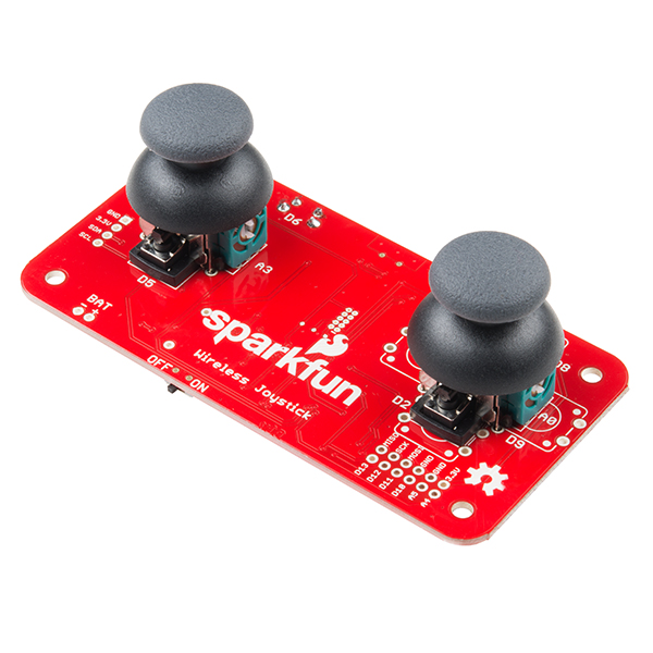
SparkFun Wireless Joystick Kit
The SparkFun Wireless Joystick Kit provides an easy way to control your next XBee project. Before the wireless joystick, radio-controlled projects used hobby RC transmitters, the same ones used for RC cars, boats and planes. The problem with these transmitters is that many aren’t customizable, and the ones that are tend to be too expensive for many of us. The Wireless Joystick Kit offers a custom wireless solution for those who want to control their project their own way.
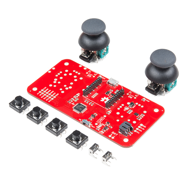
Equipped with the increasingly popular SAMD21 onboard, all you need is to assemble the SparkFun Wireless Joystick into the configuration you want and add your own XBee and lithium ion battery into the provided sockets. The Wireless Joystick Kit can be assembled into a configuration that utilizes dual joysticks for better RC steering robots (like tanks) or a single joystick configuration with four 12mm momentary pushbuttons (a setup similar to what older game consoles used). There's also a built-in LiPo charge IC (MCP73831) and fuel gauge (MAX17043). We have provided a full Hookup Guide that gives assembly instructions, as well as a tank-steering motor controller tutorial to help get you started!
Please be aware that the SparkFun Wireless Joystick Kit is NOT supported on Windows 7/8 due to a lack of support drivers for those specific OS's.
Note: This kit will need to be assembled before use, so a beginner's knowledge of soldering will be required. Additionally, in an effort to keep shipping rates down and make this kit available to people throughout the world without delay, there is no XBee or lithium ion battery included.
- 1x Wireless Joystick Board
- 2x Right Angle Tactile Button
- 2x Thumb Joysticks
- 4x Momentary Pushbutton Switch - 12mm
- Schematic
- Eagle Files
- Hookup Guide
- Datasheet (ATSAMD21G18)
- GitHub Hardware Repo
SparkFun Wireless Joystick Kit Product Help and Resources
Wireless RC Robot with Arduino and XBees
March 12, 2019
In this tutorial, we will expand on the SIK for RedBot to control the robot wirelessly with XBee radios! We'll explore a different microcontroller and wirelessly control the RedBot at a distance.
SAMD21 Mini/Dev Breakout Hookup Guide
November 12, 2015
An introduction to the Atmel ATSAMD21G18 microprocessor and our Mini and Pro R3 breakout boards. Level up your Arduino-skills with the powerful ARM Cortex M0+ processor.
Adding More SERCOM Ports for SAMD Boards
February 4, 2019
How to setup extra SPI, UART, and I2C serial ports on a SAMD-based boards.
Micro OLED Breakout Hookup Guide
October 30, 2014
Learn how to hook up the Micro OLED breakout to an Arduino. Then draw pixels, shapes, text and bitmaps all over it!
Wireless Joystick Hookup Guide
January 5, 2017
A hookup guide for the SparkFun Wireless Joystick Kit.
LiPo Fuel Gauge (MAX1704X) Hookup Guide
February 23, 2023
Monitor your LiPo battery with the LiPo fuel gauge! In this tutorial, we will be using the MAX17043 and MAX17048 to monitor a single cell, LiPo battery over the Arduino Serial Monitor. We will also connect a display to view the output without the need to connect the microcontroller to a computer.
Core Skill: Soldering
This skill defines how difficult the soldering is on a particular product. It might be a couple simple solder joints, or require special reflow tools.
Skill Level: Rookie - The number of pins increases, and you will have to determine polarity of components and some of the components might be a bit trickier or close together. You might need solder wick or flux.
See all skill levels
Core Skill: Programming
If a board needs code or communicates somehow, you're going to need to know how to program or interface with it. The programming skill is all about communication and code.
Skill Level: Rookie - You will need a better fundamental understand of what code is, and how it works. You will be using beginner-level software and development tools like Arduino. You will be dealing directly with code, but numerous examples and libraries are available. Sensors or shields will communicate with serial or TTL.
See all skill levels
Core Skill: Electrical Prototyping
If it requires power, you need to know how much, what all the pins do, and how to hook it up. You may need to reference datasheets, schematics, and know the ins and outs of electronics.
Skill Level: Rookie - You may be required to know a bit more about the component, such as orientation, or how to hook it up, in addition to power requirements. You will need to understand polarized components.
See all skill levels
Comments
Looking for answers to technical questions?
We welcome your comments and suggestions below. However, if you are looking for solutions to technical questions please see our Technical Assistance page.
Customer Reviews
4 out of 5
Based on 2 ratings:
1 of 1 found this helpful:
Good kit
This is a good kit - works as designed and, most importantly is fully re-programmable.
We are in the process of making it work using our own firmware (sans arduino) and our own mesh radio. Early days, but if anyone interested we can post back when we have demo.
Very good kit but...
Works very good but it would be nice if the XBee pins were brought out to pads since some of the XBee variants require extra signals. The small header pads under the XBee appear to be for testing.
It would also be nice if a housing was available or the board size fit an existing housing.
now if only you still carried these: https://www.sparkfun.com/products/retired/10314
It seems to me that the SAMD21 is overkill for this. Wouldn't a 32u4 work just as well and be cheaper to source the parts for? How much memory and speed do you really need to read several switches and analog inputs then spit the formatted data out over a UART port (to the XBee)?
Or is ATMEL trying to EOL the 32u4?
Also, the configuration of the pins on the SAMD21 is nice giving you a few more options when it comes to configuring the remaining pins that are broken out (more analog, serial, etc.)
A 32u4 would work just as well, and the prototype for this board actually did use a 32u4. As it turns out, the SAMD21 is actually less expensive to use and that's one of the reasons we went with it over a 32u4. We're still getting our feet wet with the SAMD21 but expect to see it in more future designs.
I don't know if ATMEL is planing on EOL the 32u4 anytime, you'd have to ask them that. I haven't seen any documentation that hints at it going EOL so it should be safe for the time being.
Good reasonings from both.
@CF - yes less expensive (as contrasted to "cheaper") is preferable.
@M-Short - I had forgotten about the SAMD21's flexible pin configurations. Thanx for the reminder.
Picked this up for a project and designed a gamepad frame for it. Thought someone else might want to print one for theirs. It still has a DIY "robo" feel to it with the exposed board.
https://www.thingiverse.com/thing:4868029
Does this now work with windows 7? (https://www.sparkfun.com/news/2937)
Yes, that is correct. As mentioned in this blog post, we have updated the drivers for Windows 7. Follow the instructions in the blog post/tutorial to update your drivers. Keep in mind, that you will need to force the board into the "bootloader mode" to upload code.
Can we get a version with ESP wifi instead of XBee?
This is really cool, thanks for inventing it.
Is there a CAD (.step) file of the physical thing available? I'd like to make a thing that goes around it.
The only CAD files we currently have are the Eagle files, where there are measurements on layer 47. But if you make a case for it, let us know!
https://grabcad.com/library/wjk_body-1
It only fits one battery size and you need a 3D Printer.
Your GitHub link is broken.
Fixed the issue, sorry about that!