- Home
- Product Categories
- Infrared
- SparkFun Line Sensor Breakout - QRE1113 (Analog)

SparkFun Line Sensor Breakout - QRE1113 (Analog)
This version of the QRE1113 breakout board features an easy-to-use analog output, which will vary depending on the amount of IR light reflected back to the sensor. This tiny board is perfect for line sensing applications and can be used in both 3.3V and 5V systems.
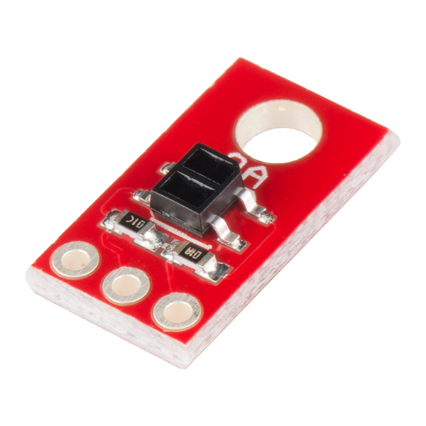
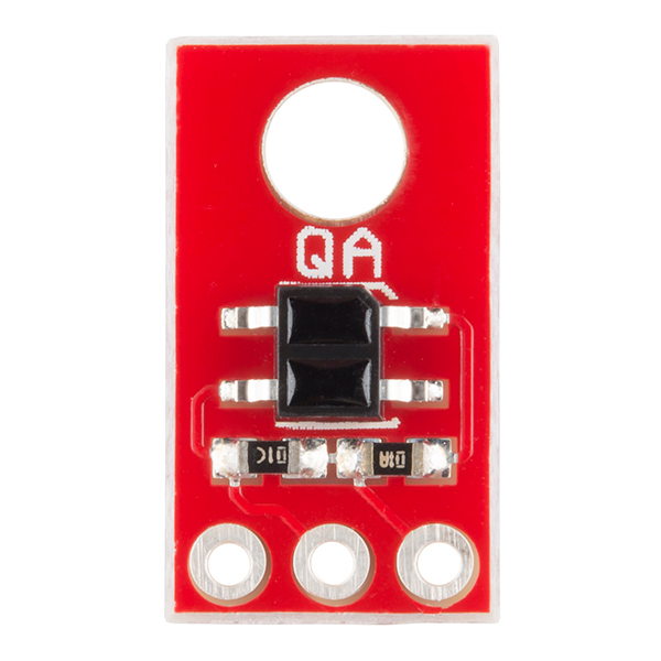
The board's QRE1113 IR reflectance sensor is comprised of two parts - an IR emitting LED and an IR sensitive phototransistor. When you apply power to the VCC and GND pins the IR LED inside the sensor will illuminate. A 100Ω resistor is on-board and placed in series with the LED to limit current. A 10kΩ resistor pulls the output pin high, but when the light from the LED is reflected back onto the phototransistor the output will begin to go lower. The more IR light sensed by the phototransistor, the lower the output voltage of the breakout board.
These sensors are widely used in line following robots - white surfaces reflect much more light than black, so, when directed towards a white surface, the voltage output will be lower than that on a black surface.
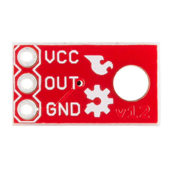
The power input and analog output pins are brought out to a 3-pin, 0.1" pitch header. The board also has a single mounting hole if you want to screw the board onto something.
We also have a digital version of this board.
- 5VDC operating voltage
- 25mA supply current
- Optimal sensing distance: 0.125" (3mm)
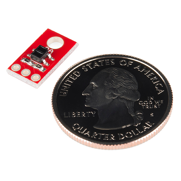
- 0.30 x 0.55 " (7.62 x 13.97 mm)
- Schematic
- Eagle Files
- Datasheet (QRE1113GR)
- Bildr Tutorial
- GitHub
SparkFun Line Sensor Breakout - QRE1113 (Analog) Product Help and Resources
Core Skill: Soldering
This skill defines how difficult the soldering is on a particular product. It might be a couple simple solder joints, or require special reflow tools.
Skill Level: Noob - Some basic soldering is required, but it is limited to a just a few pins, basic through-hole soldering, and couple (if any) polarized components. A basic soldering iron is all you should need.
See all skill levels
Core Skill: Programming
If a board needs code or communicates somehow, you're going to need to know how to program or interface with it. The programming skill is all about communication and code.
Skill Level: Noob - Programming will be limited to basic drag and drop interfaces like ModKit or Scratch. You won't be writing code, but you will still need to understand some basics of interfacing with hardware. If you?re just using a sensor, it's output is analog.
See all skill levels
Core Skill: Electrical Prototyping
If it requires power, you need to know how much, what all the pins do, and how to hook it up. You may need to reference datasheets, schematics, and know the ins and outs of electronics.
Skill Level: Noob - You don't need to reference a datasheet, but you will need to know basic power requirements.
See all skill levels
Comments
Looking for answers to technical questions?
We welcome your comments and suggestions below. However, if you are looking for solutions to technical questions please see our Technical Assistance page.
Customer Reviews
4.7 out of 5
Based on 3 ratings:
2 of 2 found this helpful:
Works (surprisingly) well
Used this sensor (duh) for a line following robot. I had previously used its much larger cousin, the QRD1114, with little success. However, no issues with this sensor: it was able to cleanly and consistently sense black electrical tape against wood, provided that the sensor was very close (within 1cm of the ground).
Works as Intended.
The sensor works and outputs an analog voltage level relative to object distance. Read the data sheet and notice that the intended detection range is only 3mm which is quite short. This was a little to small for my particular application, but I got it to work. Other than that, this is one of the smallest proximity sensor breakout boards available if you really need to get it into a tight spot. Good product.
This can also be used as a crude, inexpensive heart rate monitor by taping it to your finger. As the blood pumps through, the lightness/darkness of your finger changes slightly to infrared, and this signal can be picked up by ADC and filtered to find peaks in order to find your heart rate.
I'm shopping for parts for a pulse oximeter project. Would anyone happen to know the specific wavelength of the emitter?
Peak emission wavelength at 20 mA is 940 nm.
I think I heard about 910nm was perfect, so this works for me. Thanks.
Can someone please explain to me why it appears that the phototransistor side appears to be connected backwards from what the pinout on the data sheet says? Looks like collector is connected to GND and the emitter to VCC. Schematic and Eagle file have pins 3 and 4 swapped (opposite) from how the data sheets shows them...
Tried using these to detect the needle passing on my water meter but they didn't seem to have the range (possible glare from the plastic face too).
This is outputting a constant 5 volts no matter how dark the object being sensed is. Can anyone help?
Trying to figure out the bandwidth - if I read the datasheet correctly, at a 10khz load, doubling the worst case rise/fall time should be about 5khz, or 15khz with a 1k load?
My application is simple object detection (a ball passing through a chute), and I was initially very dissatisfied with the range of this circuit.
In my case, my ADC Vref was hardwired to 3.3V, and I finally figured out why this limited range to about 1 centimeter. Running at 3.3V and 5V were both limited, the former because the IR output was too dim, the latter because the top of my Vout range was clipped by the ADC VREF.
I ended up powering with 5V and adding a 10K resistor between OUT and GND. This allowed full-power IR led and cut my max Vout in half (2.5V), bringing the full range below my ADC Vref, which increased the sensing range of this unit to a full inch (2.5 CM).
In the same way, you can hook this directly to a microprocessor's digital input by matching the value of this added OUT/GND resistor to your digital input characteristics (you'd want your IR Vout max just above the digital input's Vmax for a low signal).
Also note that incandescent light (from standard tungsten bulbs) will throw the sensor way off as it's much stronger than the reflected IR light. I haven't tested sunlight, but I assume it'll have a similar effect. I'm using my microcontroller to calibrate the analog input to account for ambient light, which should work in low/indirect indoor light.
If I just want this to tell me black/white, can I connect these to an Arduino digital input pin and use a trimpot to adjust the sensitivity?
The emitter current limiting resistor on the analog versions that are shipping October 2012 are measuring to be 100 ohms. The sensors are actually running pretty warm. The emitters are drawing 34mA at 5V - but a perfect 20mA at 3V3. I know the datasheet has absolute maximum ratings of 50mA, but... I have four of them runing at 5V and they're all running just over 100ºF. Are we sure this is OK?
I have the same "issue". I don’t know if this is ok...
how can you connect those as an array like 3 or 4 in a row?
Can anyone tell me the range on these? I've got several (analogs), for line following, but they only seem to work under 1 cm.
Say I was using this with an Arduino Duemilanove. I think (I may be wrong) the analog inputs on it measure current, not voltage. So when you said "the lower the output voltage" did you mean current?
Also, it says "We also have an digital version of this board" at the end of the description.
They definitely mean voltage.
Analog inputs on microcontrollers measure voltage.
Speaking of Arduinos, here is an Arduino library for reading Pololu's version of this sensor. It should work for the Sparkfun version as well.
Thanks!
These are great sensors. I'm going to see if I can make a heart rate monitor as davr mentioned.
Re the current limiting resistor, it is actually 150 ohm. I'm replacing it with 100 ohm to make the sensor function at 3.3V. (Note, the 8x strip is configurable to work at both voltages; this one isn't.)
What are the SMD packages for the resistors? I want to replace them too.
Just in case anyone is wondering, I emailed tech support and they confirmed the BOM has a 100ohm resistor for current limiting on the LED. I've yet to land these in my hands, but I'll post back if they're not actually 100ohm.
I'm glad you carry these now. I bought the digital version by mistake, but converted them to analog by removing the cap and adding the appropriate resistor. Kludgey, but it works.
You ought to make a breakout board for the Hamamatsu P5587: it's got a built in Schmidt trigger, so it's great for wheel encoders.
The analog version is typically easier to use, but the digital version has a few benefits that make me prefer them on my robots:
1) They don't take up valuable analog inputs.
2) Multiple digital modules can be read in parallel while analog modules must be read sequentially if your MCU only has one ADC unit.
3) The digital version can see farther with more resolution (see this app note for more info), though this added resolution comes at the cost of a decreased sample rate.
Note that the Pololu QTR sensors no longer use the QRE1113; they now use a similar generic unit that has a slightly longer range.