- Home
- Product Categories
- Audio
- SparkFun MIDI Breakout

SparkFun MIDI Breakout
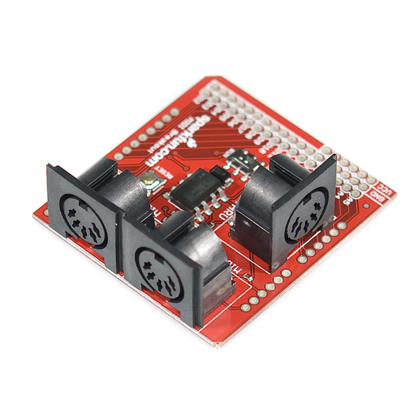
The SparkFun MIDI Breakout board gives your Arduino or any other microcontroller access to the powerful MIDI communication protocol. The MIDI protocol shares many similarities with standard asynchronous serial interfaces, so you can use the UART pins of your microcontroller to send and receive MIDI's event messages.
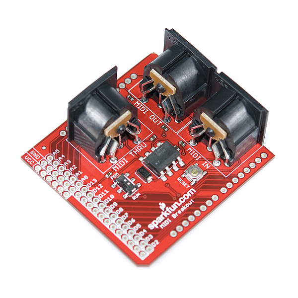
The SparkFun MIDI Breakout provides both MIDI-IN and MIDI-OUT connections, as well as a MIDI-THRU port. The MIDI-IN port is opto-isolated to prevent ground loops. The MIDI Breakout board can be mounted directly on top of an Arduino like a shield, connecting the MIDI-IN/THRU to the Arduino's hardware RX pin and the MIDI-OUT to TX. All of the Arduino's digital and analog pins, as well as power and ground busses, are broken out as well. The RUN/PGM switch allows you to program the Arduino over serial without having to remove the shield.
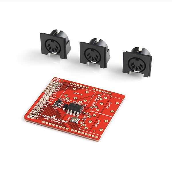
**Note: **The MIDI Breakout does not come with the three through-hole MIDI connectors soldered; these connectors are included with the product, however.
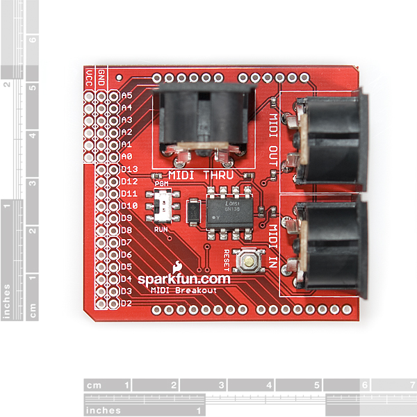
- 2.25 x 2.10 " (57.15 x 53.34 mm)
SparkFun MIDI Breakout Product Help and Resources
Core Skill: Soldering
This skill defines how difficult the soldering is on a particular product. It might be a couple simple solder joints, or require special reflow tools.
Skill Level: Rookie - The number of pins increases, and you will have to determine polarity of components and some of the components might be a bit trickier or close together. You might need solder wick or flux.
See all skill levels
Core Skill: Programming
If a board needs code or communicates somehow, you're going to need to know how to program or interface with it. The programming skill is all about communication and code.
Skill Level: Rookie - You will need a better fundamental understand of what code is, and how it works. You will be using beginner-level software and development tools like Arduino. You will be dealing directly with code, but numerous examples and libraries are available. Sensors or shields will communicate with serial or TTL.
See all skill levels
Core Skill: Electrical Prototyping
If it requires power, you need to know how much, what all the pins do, and how to hook it up. You may need to reference datasheets, schematics, and know the ins and outs of electronics.
Skill Level: Rookie - You may be required to know a bit more about the component, such as orientation, or how to hook it up, in addition to power requirements. You will need to understand polarized components.
See all skill levels
Comments
Looking for answers to technical questions?
We welcome your comments and suggestions below. However, if you are looking for solutions to technical questions please see our Technical Assistance page.
Customer Reviews
4 out of 5
Based on 1 ratings:
Hello, Just to know about the availability of this product, I read on two electronics forums that this product will be replaced by the Midi shield DEV-09595. Is that correct or is it just a rumour? I hope this is just a rumour cause I really often use this product in my job.
Best regards
Too expensive for such a bad design. TX input for MIDI OUT should be buffered.
The Logic Level output is far under 5V... around 1V. Really bad Product...
Why isn't there a new revision of this board? Isn't the 6N138SM a replacement for the discontinued 6N138S used in this board?
How can they NOT label the headers so we know how to connect this to a µController or other device?
I bought this from ABRA Electronics in Montreal Canada. There were no papers with it at all. RX and TX not marked. Voltage input not clear and your schematic online is just DOTS !!
I'm trying to develop a MIDI product using the PIC CHIP and I thought that this would save me time ????????????????????
DAN
Regarding the schematic, the PDF viewer built into Firefox seems to be having a lot of problems. Try downloading the file and viewing it using Acrobat Reader or another PDF viewer on your computer. This should answer some of your questions.
You're right that there should be more labeling on this board than there is. This board is meant to be an Arduino "Shield" which has common pins in fixed positions. You can certainly use it with a PIC or any other microcontroller though. I've put up a picture showing the positions of the pins you need at: http://dlnmh9ip6v2uc.cloudfront.net/datasheets/BreakoutBoards/MIDI_breakout_pinlabels.png. We also supply the EAGLE files for this board. EAGLE is the software we use to design all our PCBs, and is available from www.cadsoftusa.com. If you install EAGLE and load the board file, you can see which lines go where.
Sorry for the confusion, I hope this helps you get up and running.
EDIT: This board is meant to run on 5V.
Does anyone know which holes TX(D1) and RX(D0) are on the board? They're not labeled
We'll get the Eagle files posted asap. You can use those to trace out any pins on the board that you need. If you don't have Eagle, you can download a free version here.
Hmm, the width on the board between the 8 pin headers doesn't seem to match exactly with Arduino.
Still works if you put the stackable headers on slightly at an angle, though.
Hm, looks right to me. Maybe your Arduino is slightly off? (Then again, I'm using Sparkfun's arduino breakout footprints on all my stuff, so it's not surprising that it matches this board. But I find it hard to believe that all of Sparkfun's products have the wrong spacing here...)
Very beautiful prints! This has convinced to me to go deeper into Arduino.
In the earlier comments I read that both MIDI shield and MIDI Breakout are suitable for Arduino. But when I click on the Arduino MIDI Tutorial, such a print is completely left out. What is wise to do?
Greets, Richard
You can use either the shield or the breakout board with your Arduino. The Arduino MIDI tutorial is just showing a very basic MIDI jack connected to the Arduino. Check around on the forums if you would like to see examples of how customers have used both the breakout board and the shield in their projects.
I ordered this (BOB-09598), received a bag labeled BOB-09598 but the board inside is actually the DEV-09595. Seems like there was a mistake in kitting.
Sorry to hear about the mix-up. If you haven't gotten this taken care of yet, please email us at techsupport at sparkfun dot com with your order number and we can get that fixed for you.
In the schematic, it looks like pins 4 and 5 are reversed for all the MIDI connectors.
The label on the schematic for the connector is misleading. MIDI is a differential signal on a unidirectional cable. There's no "in" and "out", there's just "plus" and "minus" of the differential current signal. Compare to http://www.midi.org/techspecs/electrispec.php . It looks right to me.
Im using this board with an Arduino Pro 5V (DEV-09219).
In order to get it to work with the Arduino Pro I had to bypass the 1k resistors on the RX and TX lines (D0 and D1) on the Arduino Pro. Im not sure why the resistors are in-line to pins D0 and D1, because they are not in the Regular Arduinos, nor are they on the Pro Minis.
It worked perfect with my Uno and my Duemilanove.
Im mentioning it to save some other sucker a few hours of troubleshooting. UGH.
"a few hours of troubleshooting"? This sucker (me) spent a week in despair and frustration! Even bought a second Pro board to rule out broken hardware. I guess the idea with the resistors is to ensure priority for the USB serial connection (with an FTDI) over the D0/D1 UART. As you say, it is not on th Pro Mini, but some other boards have it the other way around, ie resistors "blocking" the USB serial if there is a conflict in use.
Would you believe I just got "got" again?? Grabbed a spare Arduino Pro 5V to do something with a WiFly module and spent several hours trying to figure out why it wont talk through the serial. It was those dang resistors again.
I am having trouble receiving MIDI messages with this, sending works fine, and I'm wondering if it is because I didn't connect the MIDI thru jack? I didn't bother to connect it because, first I don't need it, but also because the jack is blocked by stackable pin headers. Is the MIDI thru jack required to complete the circuit? Or does my problem lay elsewhere?
No, you do not need the MIDI THRUH jack to receive MIDI. I usually use it without it.
Make sure that the switch is set to "PGM" when you program the micro (or disconnect your MIDI) and it is set to "RUN" when you use it (if it is set to to "PGM" you will not be able to receive MIDI messages).
Can someone tell me what the difference between this and the 20$ MIDI shield is?
The MIDI shield is pretty similar to this MIDI Breakout, but it has additional features (2 LEDs, 3 buttons, and 2 pots)
How stackable are these? I'd like to use these with a mega and have one of these hooked to each of the four uarts. Better to just use a proto board?
The MIDI connectors are pretty tall - so stacking is not easy, but possible. Also the RX and TX are hardwired, so unless you cut some traces it will be impossible to connect them to a different UARTs.
Are the holes next to the ones labelled D2 - D13 connected to ground?
Yes, these are ground pins. This is okay, because you can use the internal pull-up resistors, but I actually prefer the GVS (Gnd +5V Signal) layout for all proto boards...
Hi, is this compatible with the USB Host Shield from Circuits@Home?
I would like to use my USB-only controllers (AKAI LPK25 and Korg Nanokontrol) as full MIDI controllers.
where are the rx and tx pins, I don't see them on any pictures
I don't mean to sound harsh, but PLEASE next time you turn this board can you put on the non-inverting buffer as specified by MIDI.ORG? I know it looks like an optional part, but it's there not just for it's current sink ability but also protection of the CPU for when people plug the wrong cables into the wrong things. Sometimes the shortcuts just aren't worth it:
http://www.midi.org/techspecs/electrispec.php
We will take that into consideration on the next revision
Just FYI - it looks like you swapped the "kit" photos for this product and the MIDI Shield (DEV-09595). That is, the 5th picture on this page and the 4th picture here: <http://www.sparkfun.com/commerce/product_info.php?products_id=9595>
Cheers,
- Dean
Fixed now - thanks!