- Home
- Product Categories
- Arduino Shields
- ProtoScrewShield

ProtoScrewShield
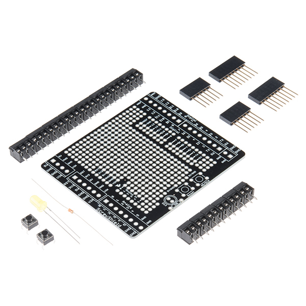
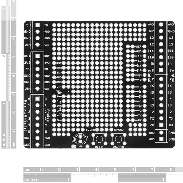
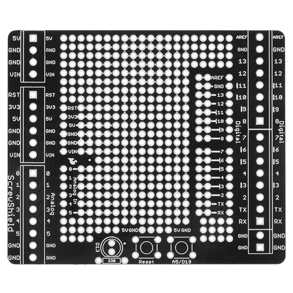
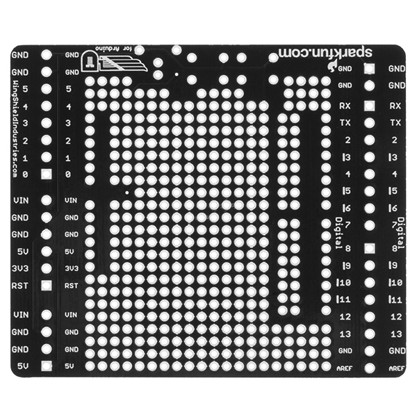
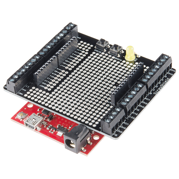
The ScrewShield extends all pins of the Arduino out to 3.5mm pitch screw terminals. It also has a lot of the utility provided by Arduino Protoshield, including: a large prototyping space of both connected and unconnected 0.1" spaced through-holes, a couple 5V and GND busses, a reset button, general use push button, and a 5mm yellow LED.
This product includes all the parts shown and comes in kit form and must be soldered together by the end user.
Note: This product is a collaboration with Tod Kurt, John Edgar Park, and Brian Jepson of WingShield Industries and a portion of each sale goes to them for product support and continued development.
- 1x ScrewShield PCB
- 1x 5mm Yellow LED
- 1x 330Ω Resistor
- 2x 6-pin Stackable Headers
- 2x 8-pin Stackable Headers
- 2x Momentary Push Buttons
- 6x 2-pin 3.5mm Screw Terminals
- 8x 3-pin 3.5mm Screw Terminals
ProtoScrewShield Product Help and Resources
Core Skill: Soldering
This skill defines how difficult the soldering is on a particular product. It might be a couple simple solder joints, or require special reflow tools.
Skill Level: Rookie - The number of pins increases, and you will have to determine polarity of components and some of the components might be a bit trickier or close together. You might need solder wick or flux.
See all skill levels
Core Skill: DIY
Whether it's for assembling a kit, hacking an enclosure, or creating your own parts; the DIY skill is all about knowing how to use tools and the techniques associated with them.
Skill Level: Noob - Basic assembly is required. You may need to provide your own basic tools like a screwdriver, hammer or scissors. Power tools or custom parts are not required. Instructions will be included and easy to follow. Sewing may be required, but only with included patterns.
See all skill levels
Core Skill: Electrical Prototyping
If it requires power, you need to know how much, what all the pins do, and how to hook it up. You may need to reference datasheets, schematics, and know the ins and outs of electronics.
Skill Level: Rookie - You may be required to know a bit more about the component, such as orientation, or how to hook it up, in addition to power requirements. You will need to understand polarized components.
See all skill levels
Comments
Looking for answers to technical questions?
We welcome your comments and suggestions below. However, if you are looking for solutions to technical questions please see our Technical Assistance page.
Customer Reviews
4 out of 5
Based on 5 ratings:
2 of 2 found this helpful:
Great for prototyping and non-permanent wiring.
I bought one to replace a fairly crowded custom shield for my proton pack. This makes it easy to route the wires to the various LEDs and other peripherals, and switch them around occasionally when needed. Since it comes as a kit, I only assembled the parts I needed.
5 of 5 found this helpful:
So far so good.
I thought that I would drop in here and hopefully prevent someone from making ugly terminals like I did :o) At least on one side anyway.
The little terminals are cool. They interlock.
Pay attention to how you assemble them and they'll nest together perfectly. Or you can stab and solder and end up fighting to keep them straight like I did on the first set :o)
Works great, needs better instructions
It would be nice to have the instructions printed in the box as well, instead of having to find them online.
The instructions are good enough, except they don't show the direction of the LED, so you have a 50/50 chance of putting the LED in wrong. It would be nice if they showed which hole the long and short pins go into. Since the rest is fairly straightforward, the instructions online work well enough.
FYI LED Orientation
Looks like a nice kit. I have used similar ones with good results. For the user who was questioning the orientation of the LED leads on the board, just look closely at the silkscreen footprint for the LED. It clearly shows the flat edge of the LED base which seems to butt up against a resistor. As long as your LED is placed on the same side as the silkscreened footprint and the flat edge is oriented as the footprint shows, you should be good to go.
Very useful for quick protoyping. The screw terminal block type is disappointing.
I purchased two of these for quickly switching instruments as projects are developed and tested. But, unfortunately the screw terminal blocks are "screw with leaf spring" type. The leaf springs bend, and remain (mostly) in the clamped position after you back out the terminal block screw. Therefore, I have to take a tiny screwdriver to poke into the opening of each terminal block to "bend up" the leaf spring, prior to attempting to insert a new wire into the terminal block.
Please, SparkFun, consider changing the terminal blocks to "rising cage clamp" type. In these type of terminal blocks, as the screw is backed out, the opening of the terminal block opens up wide; making the insertion of a new wire very easy.
NEED ONE FOR THE MEGA/ MEGA ADK!!
Second that!
Works great, Love it. Need to make one for the Mega now!!
Some assembly instructions and a schematic for the work area would be nice.
It isn't difficult to figure out but having to get a magnifying glass and follow the little path from ground to determine orientation for the LED combined with having to test a little before being able to infer that the tiny (-) signs indicate continuity was disappointing.
I spent $15 so I could get right to making something quickly. This kit falls short by a single, short paragraph of text.
Agree that the white lines could be MUCH clearer regarding what is connected.
The LED orientation is indicated by the outline on the board though - the flat on the LED matches up with the flat line on the board.
Assembly instructions here
http://wingshieldindustries.com/products/protoscrewshield-for-arduino/
The current version uses flat head screws for the 3 position terminals, and a Philips head for the 2 position terminals. On the next batch can you standardize on one or the other? My batch# is 64465. Otherwise a great board. Thanks.
The only change I'd ask for to this is another couple of screw terminals for the power pins.
Can i wire stepper motors into this, or is it better to use the Rover 5 driver shield?
I currently am using one of these on a robot for a school soccer competition. While I had this on my brand new RedBoard with a WRL-11786 and a BOB-12009 soldered to the shield, the voltage regulator on the RedBoard started overheating. I took the shield off the RedBoard and the voltage regulator cooled off. When I noticed this, I notified my teammate who soldered everything together. We double-checked all the connections, solder joints, code, and we cleared any solder debris off the shield. Same thing happened again. Turns out, using both ground holes in the board caused this. We fixed it by putting both ground wires onto two of the holes that were bridged and used a third bridged hole to connect everything to ground. We haven't had any more problems so far. Anybody have an explanation for this?
This may not be an R3 shield, but it is very handy for interfacing stuff off-board when prototyping. I combine these with the small breadboards. I need to build some that have extra terminals and headers, so I can have connections for things I add on the breadboard, like FETs. There is plenty of PTH space for more terminals. A Mega version would be very cool, but that would be a LOT of terminals.
Sparkfun needs to be clear that this is not an R3 shield. There are no SDA or SCL headers. Wish I hadn't bought this. I assumed the headers were set up for R3. I wanted to use this for a Netduino, but without the I2C pins this thing is worthless to me.
Sorry about the confusion. We do generally state R3 compatibility on any shield descriptions that are R3 layouts. Email techsupport@sparkfun and they should be able to get you set up with a return since you have no use for the shield.
Do you plan to produce a version of the ProtoScrewShield with headers to pass through the SDA and SCL pins on the R3 Arduinos? I want to use the shield with a Mega, and I don't want to lose the A4 and A5 inputs.
Just received my Protoscrew shield. I was real disappointed to find no solder pads between screw terminals and arduino pins. I don't mind cutting a trace to insert needed circuitry but I want a clean way to solder the the new circuitry in.
Adding any circuitry to this board will be a kludge, a real disappointment for a proto board,
Aren't the same pins broken out to a few pads in the proto area in the center?
I found the interconnections on this board to be extremely useful; power, ground, and IO are all close enough that LEDs, DS18B20s, etc can be connected in seconds. I never looked at a doc, the connections are all drawn fairly obviously on the board.
This board makes things so easy that I'm back here trying to buy one now even though I already have an empty basic shield already on my desk!
I was a little bummed that the screw connections are not standard perf board size, and therefore not easily interchangable with other projects. I guess it's nice that they are big though.
If you get this sheild. Be certain to download and view the Connection Diagram before you lay out anything. This board has a lot of connected pads in places you might not suspect.
Be sure your using gauge 18 or 20 wires for fitting into the screw terminals. They are itty bitty and the screws are even smaller. I have to use my smallest screw driver to operate them.
Lastly if you are trying to do any signal conditioning between the Arduino pins and the screw posts. You'll have to cut the traces between the screw pins and the Arduino pins.
I've love most everything I've ever bought from Sparkfun, but this board is not one of them. Maybe they'll come up with a rev 2 that will be a little more real estate useful.
Cheers.
Are there eagle files available for this board?
Enjoying using the ProtoScrewShield to breakout pins not in use by a motor shield. A question about the A5 button: I'd like to have this give me an input signal on A5 and want to be sure I've done this right.
I see the shield is wired so pressing the button pulls the A5 line to GND, I assume the way to get a signal on this line is to connect A5 to +5V through a 10K resistor. This works - is this the right way to do this or is there a better option?
Thanks, Alex
A variant screw shield that brings out all the pins of the Mega would be most welcome.
I've made a review of sorts of this board:
http://abiro.com/w/2011/09/21/arduino-protoscrewshield-the-electricians-dream/
If I've misunderstood something, feel free to let me know. I got and built it today, so I haven't had much time with it.
And I've still to determine what the 2D interconnected area is for. A mystery.
could i solder an arduino pro on top of this?
You mean Arduino Pro Mini? Should work, but look out for the interconnected holes.
would i b able to fit a mini breadbord on this like a proto shield i mean its cheeper and has the screw holders thingys sorry im new
You can actually fit two Breadboard Mini Self-Adhesive (see http://twitizer.com/AmhV1). In that case I recommend that you don't solder the LED and buttons, so the other board doesn't stick outside of the shield.
from the pictures it looks like it would be possible to use the mini breadboard
disappointed a little bit. No documentation on what to solder where. not all of us read schematics.
Also the board doesnt fit the UNO correctly. I mean seriously? It hits the back of the power tube and the front of the shield sticks up. It would have taken you 5 minutes to fix that before production. I will most likely return this before soldering it and buy 2 from Critical Velocity. I didnt want seperate shipping so I went with these. bad call. My CV srcew shield is great. It came with better screw thingys too. These tiny blue ones are garbage.
Also its fairly obvious this is a big sheild from the pics. But man its BIG and unweildy.
Lets hope the rest of my stuff is ok.
Just noting that the current version of this shield fits fine with an arduino UNO R3. It doesn't bring up the new pins however.
It would be nice if at least some of the screw terminals were a larger size. Currently, there are 9 GND screw terminals... I'd gladly trade 4 of those for 2 GND's that were twice as big.
The two wire pins SCL and SDA don't really matter since they are directly connected to A4/A5 on the analog side of the board.
I'm not sure how you can tell that the board hits what if you haven't soldered the headers on. Arduino shields are very hard to measure if you don't actually have the headers soldered on since the boards don't actually sit all the way on the female headers. I will look into the screw terminals but these are the same we use for many of our other products without any problem.
Thanks for pointing me to Critical Velocity for this. I just got my screw shield and am also disappointed in the cheap blue screw down terminals. Its going to be impossible to fit a decent sized wire into that.
I love everything else I've gotten from SparkFun, but the screw terminals for this left much to be desired.
I am using the screwshield for Arduino with the prototyping area in the center (not the wing shield). I was able to trace through and determine the pads that are connected but am trying to reason why you chose the pattern for connecting the pads that you did. I am attempting to place an IC on the board and it seems that I would straddle the 5V and GND pad row down the center of the board but the left side of the pins hit on the individual pads and the right side hit on the three pad group like I would expect (so I can easily make connections to the pin of the IC via the three connected pads). Should there also be a set of three connected pads for each pin on the left side also? Is there another way for placing components that is more inline with your design that I am overlooking? Help!
I couldn't get this on my Free Day order, but I'll try to fit it in with my next. Everything here is through-hole, right?
Also, DEV-07914 is listed twice in related products.
So maybe an silly question, but will the mini breadboards fit in this as well as they do for the protoshield?
You can fit two, but one of them sticks out a bit if you solder the LED and buttons.
Please see http://twitizer.com/AmhV1
They should.
Hi. Is there the pcb schematic or some sort of guide to know which pads are tied together ? Is a great shield, tied-together pads are really useful for me... but don't want to make any mistakes.
The top side shows tiny bars between the interconnected holes.
It looks like the silkscreen shows which holes are connected to which - though its a bit hard to see.
Honestly, I'm all about using it with the mini breadboard. Cop a few of those, cheap as they are, stack it up and slot it quick when the time comes. Or get a protoboard, cut it down to size and get a few spacers on it. Quick swap in multiple in progress projects, you know?
I have to say this is the first Sparkfun product I've been really disappointed with. It's a great idea but the execution here is poor, in my opinion.
I bought this because I loved the wingshield version and I liked the idea of the big proto area. However, the proto area is really confusing. Almost half of the available pads are tied together in some way or another. Also, the labeling on the underside is very confusing.
Admittedly, I'm pretty new to all of this so maybe this wouldn't be such a problem for a more experienced person. Either way, the proto area is not as large as it appears and is arranged such that it's difficult to place anything on it that is more than 3 holes wide.
You can use a hobby knife and cut the traces between holes.
It sounds hack-y but there are some prototyping systems that are built with this in mind specifically (someone help me out with a brand name).
Seems a little like a special purpose vero board or strip board like.
AWESOME!!! I got the original screwshield, but it was a little too flimsy for my use. Had a few ideas on soldering it on the bottom of a Duemilanove,or making a 'U' shaped support bracket. I LOVE combining it with proto area. What a great idea.
Now I have to make up another order...oh well!