
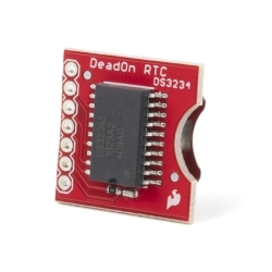
SparkFun Real Time Clock Module
Helpful Documentation
 Hookup Guide
 Schematic
 Datasheet (DS1307)
Product Overview
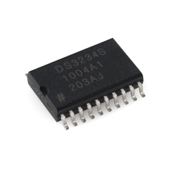
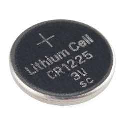
This is the SparkFun Real Time Clock (RTC) Module, this little breakout that uses the DS1307 to keep track of the current year, month, day as well as the current time. The module comes fully assembled and includes a small CR1225 Lithium coin cell battery that will run the RTC for a minimum of 9 years (17 years typical) without an external 5V power supply.
The DS1307 RTC is accessed via the I2C protocol. We've written a test-bed to program the modules, this code should give you some insight on how to interface the module to any microcontroller using our example software I2C and BCD routines.
This rev of the Real Time Clock module finally adds I2C resistors and a larger battery pad to fix the problems with the battery shorting to the board.
Features:
- Two wire I2C interface
- Hour : Minutes : Seconds AM/PM
- Day Month, Date - Year
- Leap year compensation
- Accurate calendar up to year 2100
- Battery backup included
- 1Hz output pin
- 56 Bytes of Non-volatile memory available to user
- 0x68 I2C Address
Dimensions: 0.75x0.75" (20x20mm)
Documents:
- Schematic
- Eagle Files
- Hookup Guide
- Datasheet (DS1307)
- Arduino Library
- Wiring Example
- Example 16F88 code
- Arduino Tutorial (Portuguese) Thanks Daniel Gonçalves!
- Bildr Tutorial
- GitHub (Design Files)
-
-
 SparkFun Real Time Clock Module - RV-1805 (Qwiic)
Special Price Current price: $8.33 Regular Price Original price: $18.50In stock
SparkFun Real Time Clock Module - RV-1805 (Qwiic)
Special Price Current price: $8.33 Regular Price Original price: $18.50In stock -


Features & Specs
- Two wire I2C interface
- Hour : Minutes : Seconds AM/PM
- Day Month, Date - Year
- Leap year compensation
- Accurate calendar up to year 2100
- Battery backup included
- 1Hz output pin
- 56 Bytes of Non-volatile memory available to user
- 0x68 I2C Address
- 0.75x0.75" (20x20mm)
Documentation
Customer Reviews

Stock and Customer Discounts
Available Discounts
- $17.58 | 10+ units
- $16.65 | 25+ units
- $15.73 | 100+ units