Ardumoto Kit Hookup Guide
 jimblom,
  MTaylor
Ardumoto Shield Assembly Tips
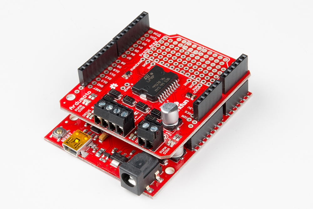
Before you can start using the Ardumoto Shield, you have to do a little assembly. Embrace your inner electronics technician and whip out that soldering iron! Time to turn a mish-mash of parts into a fully functional 'duino shield!
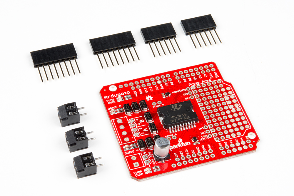
On this page we'll go over some assembly tips. You don't have to follow these steps exactly (assemble the shield as best fits your project's needs), but this is good for general use of the shield.
Add Screw Terminals (Optional)
If you please, you can add screw terminals to both of the motor outputs and/or the VIN input.
If you're adding screw terminals to the motor outputs, slide them together first:
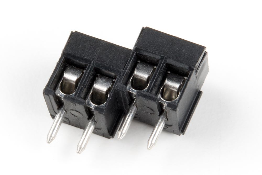
Then insert them into the shield and solder.
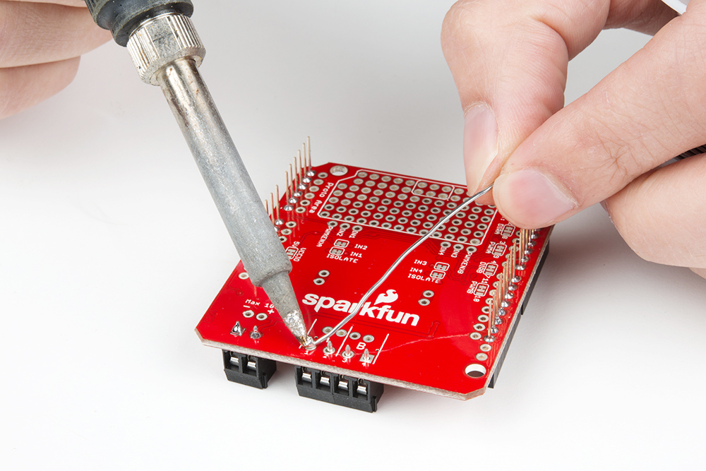
Solder the Arduino Headers
To interface the shield with your Arduino, soldering male connectors to the 28 header pins is a must. Soldering ensures a reliable physical and electrical connection. If you've never soldered before, check out our through-hole soldering tutorial.
There are usually two options for connectors when you're assembling a shield: stackable or straight. We recommend stackable headers because they allow you to stack other shields or jumper wires on top. The smaller male headers are a good option if you're looking for lower-profile installation.
If this is your first shield assembly, we recommend reading through our shield assembly guide. There are all sorts of tricks to installing shield headers, and making them look as good and straight as possible!
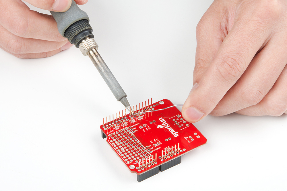
Once you're done soldering the headers, plug the shield in to make sure everything fits nice and cozy.
Prototyping Area
Let's address the elephant in the room. There's almost half a shield that we've failed to talk about thus far: the prototyping area! These rows and columns of 0.1"-spaced plated through-holes can be used to solder in all sorts of fun components.
Near the proto area is a set of six pins. With the isolation jumpers opened underneath, these allow you to interface directly to the inputs of the L298.
The six pins of the ISP connector are outlined within the proto area. These are just plated through holes, and are labeled to warn you that the pins underneath come up really close. If you absolutely need these, you may end up removing the ISP header from the attached Arduino.
Here are some ideas of what to do with it:
- Leave it alone! --- If you're happy with just driving motors, you're good to go.
- Add an accelerometer to enable bump detection in your robot.
- Fill it with LEDs to make your project as blinky as possible.
- Add current sense resistors, an op-amp, and measure the current of the motors being driven.
- Disconnect all the jumpers and wire up the L298 in any way you please.
Unlike other prototyping areas you may have encountered in the past, these holes are not wired together. You don't need to do any trace-slicing, but you will need to do some soldering and wire routing.