Big Easy Driver Hookup Guide
 Toni_K
Hardware Overview
The Big Easy Driver is designed around the Allegro A4988 motor driver. Each pin present on the board has two connection points. The first, which are the pins closest to the center of the board, are spaced out to fit standard 0.1" headers. The secondary connection points are closest to the edge of the board, and are spaced to fit 2-pin screw terminals. You can use whichever pin connections work best for your project. Functionality between the two sets does not change.
Pin Descriptions
Several pins of the A4988 IC are broken out on the Big Easy Driver, allowing direct connection to a bi-polar stepper motor, as well as a microcontroller.
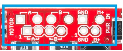
Board Top Pins
Coil A+: DMOS Full Bridge 1 Output B. Half of connection point for bi-polar stepper motor coil A.
Coil A-: DMOS Full Bridge 1 Output A. Other half of connection point for bi-polar stepper motor coil A.
Coil B+: DMOS Full Bridge 2 Output B. Half of connection point for bi-polar stepper motor coil B.
Coil B-: DMOS Full Bridge 2 Output A. Other half of connection point for bi-polar stepper motor coil B.
GND: Ground.
M+: Power supply. 8V - 35V.
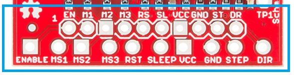
Bottom Pins
ENABLE: Logic Input. Enables the FET functionality within the motor driver. If set to HIGH, the FETs will be disabled, and the IC will not drive the motor. If set to LOW, all FETs will be enabled, allowing motor control.
MS1: Logic Input. Microstep Select 1 has a pull-up resistance of 20 kOhms. See truth table below for HIGH/LOW functionality.
MS2: Logic Input. Microstep Select 2 has a pull-up resistance of 20 kOhms. See truth table below for HIGH/LOW functionality.
MS3: Logic Input. Microstep Select 3 has a pull-up resistance of 20 kOhms. See truth table below for HIGH/LOW functionality.
| MS1 | MS2 | MS3 | Microstep Resolution | Excitation Mode |
|---|---|---|---|---|
| L | L | L | Full Step | 2 Phase |
| H | L | L | Half Step | 1-2 Phase |
| L | H | L | Quarter Step | W1-2 Phase |
| H | H | L | Eigth Step | 2W1-2 Phase |
| H | H | H | Sixteenth Step | 4W1-2 Phase |
RST: Logic Input. When set LOW, all STEP commands are ignored and all FET functionality is turned off. The translator is set to the Home state as well. This must be set HIGH to enable functionality of the motor driver.
SLEEP: Logic Input. When set to LOW, the A4988 enters sleep mode, and disables functionality of the FETs, internal current regulator and charge pump. When switching this pin to HIGH to wake up the IC, allow 1 ms of delay before sending a STEP signal. The IC will return the FETs to the home microstepping position found in the diagrams on page 14 of the datasheet upon receiving a HIGH signal on this pin.
VCC: Logic Supply.
GND: Ground.
STEP: Logic Input. Any transition on this pin from LOW to HIGH will trigger the motor to step forward one step. Direction and size of step is controlled by DIR and MSx pin settings.
DIR: Logic Input. This pin determines the direction of motor rotation. Changes in state from HIGH to LOW or LOW to HIGH only take effect on the next rising edge of the STEP command.
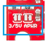
Solder Jumpers
There are two solder jumpers present on the board.
APWR - This solder jumper allows the user to use VCC as a power supply for external devices. The Big Easy Driver requires 15mA to operate, and the voltage regulator that outputs VCC can only supply 100mA. Keep this in mind when planning to power any additional devices off of VCC.
5V/3.3V - This jumper allows the user to set the configuration of VCC between 3.3V or 5V. With the jumper open, VCC will be 5V. If the jumper is closed, VCC is 3.3V.
Potentiometer
The potentiometer on board is included to allow users the ability to select the current provided to the motor. It ranges from 0mA to 2000mA (2A). This will require you to be aware what current range your motor can handle - check the motor's data sheet for the current settings.
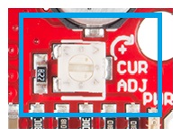
If you can't find this information, have no fear -- you can still find the proper setting for the potentiometer. First, set it to the lowest setting of the potentiometer. Keep in mind that the potentiometer is delicate, so be careful to not force the potentiometer past the mechanical stops when turning it. Once you have the motor being driven at a slow, yet steady speed, slowly turn the potentiometer and pay attention to the motor's behavior. You should find a sweet spot where the motor doesn't skip or jerk between steps.