Interactive Hanging LED Array
 Nick Poole
All Together Now
Hardware
What? You want more technical details? Well, I've got your technical details right here! Let's do the hardware first so that when we get to the code, you'll have an idea where things are connected:
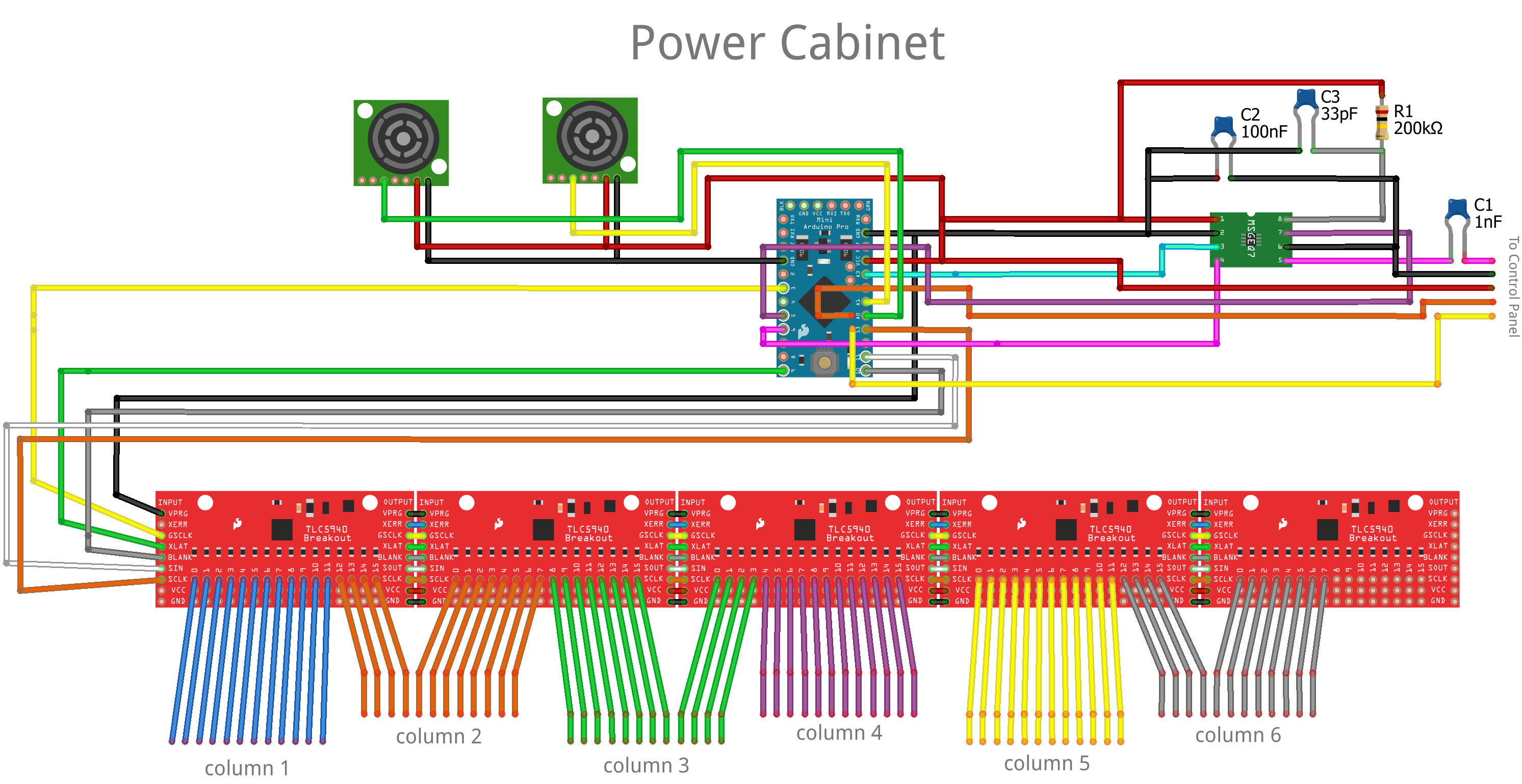
Above, you can see the hardware that we discussed in the Everything's Under Control section. In the above schematic I replaced the spectrum shield with a standalone MSGEQ7 and a handful of passives and got rid of the logic level converter. The shield will work just as well, but you're only using one of two on-board MSGEQ7s. It seemed wasteful.
You can also see that daisy-chaining the TLC5940 Breakout Board is dead easy and gives you a massive amount of control. It can be hard to tell the position of the Arduino analog connections, so here's a list:
- Ultrasonic Range Finders are connected to A0 and A1
- Momentary Pushbuttons are connected to A6 and A7
- DC Out from the MSGEQ7 goes to A3
The group of wires labeled "To Control Panel" are color coded to match the diagram below, so you can follow the connections from one drawing to the other.
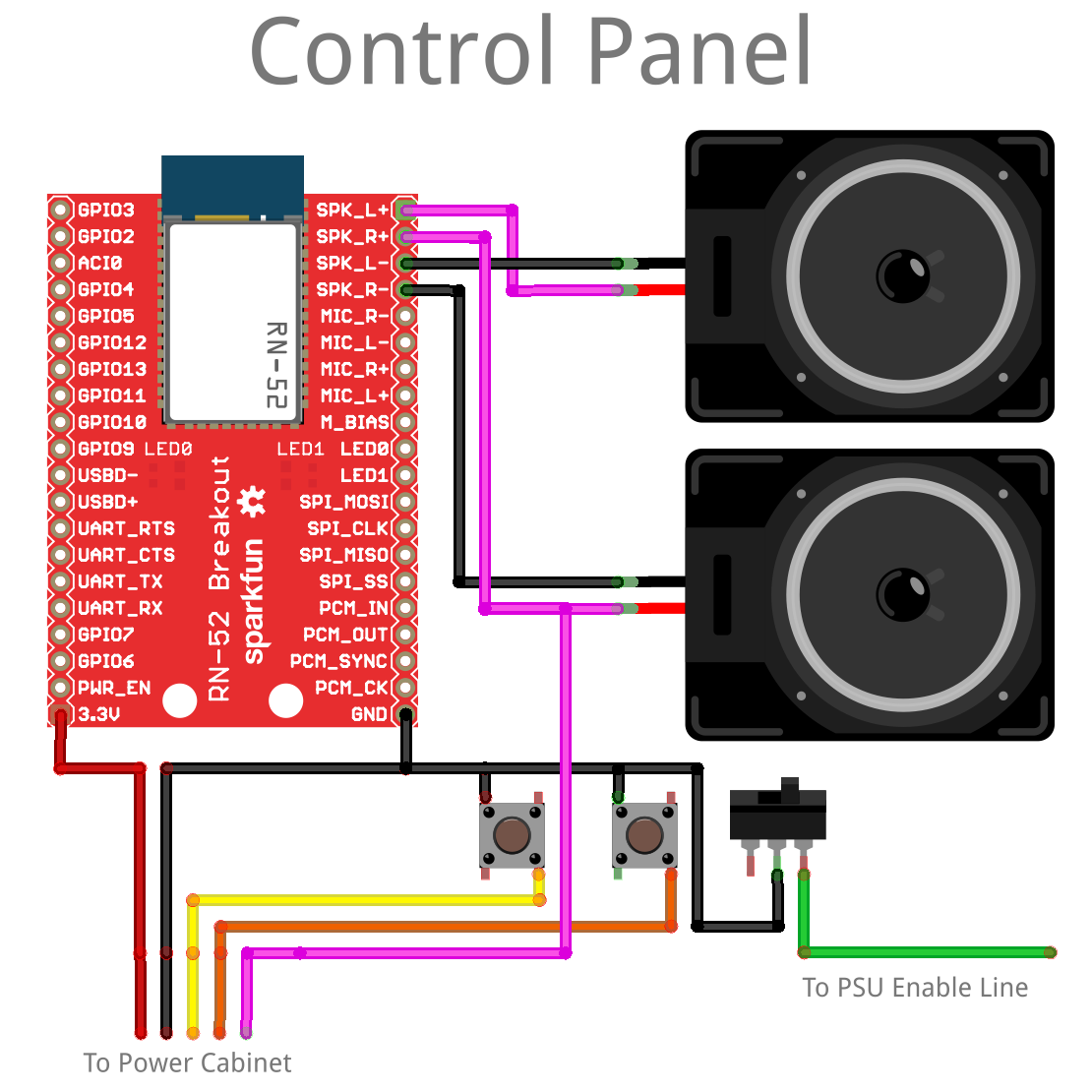
This is the control panel from the Interactivity section. There isn't a whole lot happening. The RN-52 Audio Bluetooth Breakout is doing most of the work. The audio output is differential, so, in order to feed it to the MSGEQ7, I just grabbed the positive side of one speaker and ran with it.
The line that's labeled "To PSU Enable Line" is a power switch for the whole project. It connects that green wire I told you about from the PSU to ground.
Firmware
Okay, now that we've reviewed the hardware, let's dive into the firmware. Are you ready? Too bad, we're doing it anyway!
In order to compile the code, you'll need the TLC5940 library. Let's inspect one piece of the code at a time:
language:c
#include "Tlc5940.h"

//LED Matrix Stuff

int pixel[12][6] = { //locations of LED channels in meatspace
  {56,64,44,35,15,11},
  {55,63,43,34,14,73},
  {54,62,42,33,13,9},
  {53,61,41,32,12,8},
  {60,72,40,31,23,7},
  {59,71,38,30,22,6},
  {58,70,37,29,21,5},
  {57,69,39,28,20,4},
  {52,68,48,27,19,3},
  {51,67,47,26,18,2},
  {50,66,46,25,17,1},
  {49,65,45,24,16,0}
};

int pixelstate[12][6] = { //LED PWM values
  {0,0,0,0,0,0},
  {0,0,0,0,0,0},
  {0,0,0,0,0,0},
  {0,0,0,0,0,0},
  {0,0,0,0,0,0},
  {0,0,0,0,0,0},
  {0,0,0,0,0,0},
  {0,0,0,0,0,0},
  {0,0,0,0,0,0},
  {0,0,0,0,0,0},
  {0,0,0,0,0,0},
  {0,0,0,0,0,0},
};

  int x;
  int y;

// Sensor Stuff
  int lvldoor;
  int lvlwall;

// Pseudo-Radnom Stuff
  int dice;

// Mode Stuff
boolean modeflag = 0;

// Pong Stuff
boolean xdir=0;
boolean ydir=0;
boolean movecycle=1;

// Spectrum Analyzer Stuff
int Spectrum[7];
int spectrumReset=5;
int spectrumStrobe=6;
int spectrumAnalog=3;
int scaleFactor = 15;
The first two arrays in this sketch are the heart of the operation. The first one relates the TLC5940 channel number to each LED's actual location in the grid. The second table allows the controller to keep track of the brightness level of every bulb on the grid. It's like a screen buffer in that way. I can animate by moving things around on the pixelstate array and then once it's updated I just write every location x of pixelstate[][] to every location x of pixel[][].
The integer variables x and y are used in tasks where I need to navigate one of the aforementioned arrays. The variables lvldoor and lvlwall are used to store the values coming from the two range finders. They're named that way because they contain the "level" of the reading from either the "wall" side of the room or the "door" side of the room. The variable dice is used, as its name implies, to store a randomly generated integer. The mode flag boolean keeps track of which mode we're in (pong or music-reactive). The rest of the variables that are initialized above are used in later sections, so I'll cover them when we get there.
language:c
void setup()
{

  Tlc.init();

  pinMode(spectrumReset, OUTPUT);
  pinMode(spectrumStrobe, OUTPUT);

    //Init spectrum analyzer
  digitalWrite(spectrumStrobe,LOW);
    delay(1);
  digitalWrite(spectrumReset,HIGH);
    delay(1);
  digitalWrite(spectrumStrobe,HIGH);
    delay(1);
  digitalWrite(spectrumStrobe,LOW);
    delay(1);
  digitalWrite(spectrumReset,LOW);
    delay(5);

    pinMode(A6, INPUT);
    pinMode(A7, INPUT);
    digitalWrite(A6, HIGH);
    digitalWrite(A7, HIGH);

}
The setup is pretty straight-forward for this sketch. All we're doing is initializing the TLC5940 library, the MSGEQ7 spectrum analyzer, and the button inputs. The main loop starts with two lines of code to determine whether it's time to switch modes or not:
language:c
  if(digitalRead(A6)==LOW){modeflag=0;};
  if(digitalRead(A7)==LOW){modeflag=1;};
This line is simply looking for a button press, and, if there is one, switch modes. The first of the two modes is the simplest, and that's music reaction mode:
language:c
if(modeflag==0){
  readSpectrum();

for (int y=0; y<6; y++){ // y sweep to wall
  for(int x=(Spectrum[y]/scaleFactor); x>=0; x--){
  Tlc.set(pixel[x][y], 4000);}};

Tlc.update();
delay(50);
Tlc.clear();}
The procedure call to readSpectrum() simply fills the Spectrum[] array with updated values for each of the 7 different frequency bands. Following that, it uses a for-loop to display each value as a number of lit bulbs in each of the 6 columns of lights. I had to lose a frequency band, but it's no big deal. Finally, the display is updated. There's a moment to take in the spectacle, and then it gets cleared for the next set of values.
Pong is a little more involved, I'll dump the code here, and then we'll review it:
language:c
if(modeflag==1){

    !movecycle;

//reach into meatspace
  lvldoor = map(analogRead(A0), 40, 200, 2, 0);
  lvldoor = constrain(lvldoor,0,2);

//move the ball
if(movecycle){
  if(xdir==0 && x<10){x++;}
  if(xdir==1 && x>=1){x--;}
  if(xdir==0 && x==10){xdir=1;};
  if(xdir==1 && x==1){xdir=0;};

  if(ydir==0 && y<5){y++;}
  if(ydir==1 && y>=0){y--;}
  if(ydir==0 && y==5){ydir=1;};
  if(ydir==1 && y==0){ydir=0;};}

//light the ball
  pixelstate[x][y]=4000;

//check if lose
  if(x==10 && lvldoor*2!=y && (lvldoor*2)+1!=y){
    loseCondition();
  }

//fade the field (tail on the ball)
  for (int y=0; y<6; y++){
  for(int x=1; x<11; x++){
  if(pixelstate[x][y]>0){
  pixelstate[x][y]=pixelstate[x][y]-1000;}
}
}

//ballfield update
for (int y=0; y<6; y++){
  for(int x=0; x<12; x++){
  Tlc.set(pixel[x][y], pixelstate[x][y]);}
};

//Paddles Cleanup
for(int i=0; i<6; i++){
 Tlc.set(pixel[0][i], 0);
 Tlc.set(pixel[11][i], 0);
}

//Paddles update
 Tlc.set(pixel[11][lvldoor*2], 4095);  Tlc.set(pixel[11][(lvldoor*2)+1], 4095);

Tlc.update();

delay(250);
}

void loseCondition(){

  for (int iterate=0; iterate<50; iterate++){

    for (int channel = 0; channel < NUM_TLCS * 16; channel ++) {
    dice = random(0,50);
    Tlc.set(channel, dice*80);
    Tlc.update();
    }
delay(75);
  };
}
The first line of code in the pong game flips a boolean value so that part of the code only runs every other cycle. This allows the paddle to move faster than the ball, to give the human player a sporting chance. Next, the game has to know where the player is standing in relation to the ultrasonic sensor, so we take an analog reading, map it to the 3 possible paddle positions, and make sure it's constrained properly.
Next comes the part of the code that only runs during the "move" cycle. This is really the heart of pong, as a game. This set of rules governs which direction the ball moves in and when as well as the behavior of the ball when it bounces. By the time this code has executed, the x and y integer variables will contain a new position for the ball. The next piece of code labeled "light the ball" sets that location to almost full brightness.
Of course if you can't lose, it's not much of a game, so the next piece of code checks to see if the game is lost. This rule basically reads, "if the ball and the paddle occupy the same row but not the same pixel, you lose," and it runs a procedure called loseCondition, which puts on a little lightshow.
While playing the alpha version of this sketch, I realized that it's hard to track the ball as it moves around because the playing field is so low resolution. To fix that I decided not to clear the entire field between frames but to simply dim it, causing the ball to have a short "tail" on it. This makes it a lot easier to see and more fun to play. The code responsible for creating the tail just iterates over the entire playing field checking to see if each pixel is off, and, if it isn't, it gets dimmed by a certain factor. If you change the dimming value, you change the length of the tail.
Now it's time for some housecleaning. The code labeled "ballfield update" writes all of the frame changes we just made to the TLC library's buffer. Then the "Paddles cleanup" code turns off all pixels on the paddle row before "Paddles update" lights the correct pixels for the current range finder data.
Finally, the TLC library updates the pixel data for the LEDs and a short delay is inserted to make the game playable. In the future, I may decrement this delay value as the game goes on.
I included the loseCondition() procedure above so you could see how to make a simple but dazzling lightshow. All that this procedure does is to assign a random value to each pixel on the table before updating the display, pausing, and doing it again. The effect is a lot like static on an old TV. It's running inside a for-loop so that it will only do this a few seconds before returning you to the game.
That's really it! There isn't a whole lot of code thanks to the TLC library taking care of the really hard work. Now what do you say we sit back and take a moment to enjoy what we've built? ...