- Home
- Product Categories
- Power Connectors
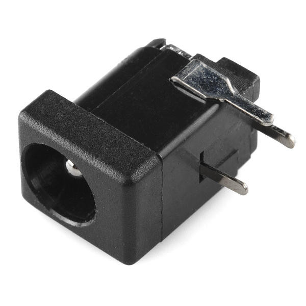
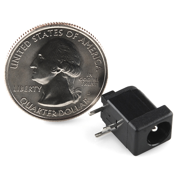
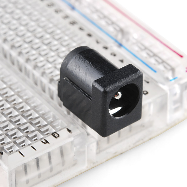
- DC Barrel Jack Adapter - Breadboard Compatible

DC Barrel Jack Adapter - Breadboard Compatible
This DC power jack/connector is just like the other one that we carry except that it's terminated with breadboard-friendly pins instead of wide solder terminals. These are also compatible with our DC wall supplies and have a 5.5mm jack, with a 2.1mm center pole diameter.
DC Barrel Jack Adapter - Breadboard Compatible Product Help and Resources
Prototype Wearable LED Dance Harness
February 8, 2018
A project tutorial to add an extra effect for dancers performing a choreographed piece. The harness can be added quickly under a costume.
Motion Controlled Wearable LED Dance Harness
January 30, 2019
Control LEDs based on your movement using an accelerometer! Make your LEDs breathe by fading in and out when laying on the floor, turn off the LEDs when moving to your side, or make the LEDs blink in a headstand!
Connector Basics
January 18, 2013
Connectors are a major source of confusion for people just beginning electronics. The number of different options, terms, and names of connectors can make selecting one, or finding the one you need, daunting. This article will help you get a jump on the world of connectors.
Pinout
The pinout of the breadboard compatible is the same as the image shown below.
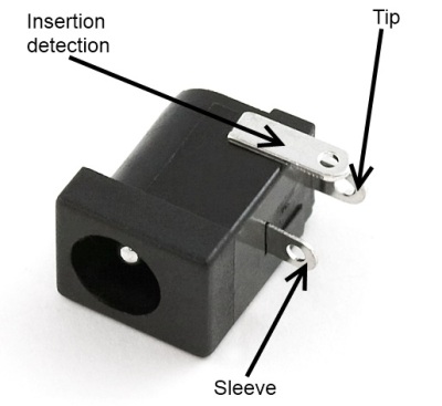
Image from the Connector Basics: Power Connector Tutorial
To connect to the DC barrel jack adapter using a center positive power supply, the pinout of the barrel jack adapter is:
Barrel Jack = Pinout
Center "Tip"= Vcc, pin opposite of barrel jack input that is usually your "**+**" input voltage
Shunt = side pin opens when a plug is inserted into the jack
Sleeve = GND, pin closest to the barrel jack's input and it is usually "**-**"  ground
Make sure to test your circuit's connection with a multimeter set to measure before powering up.
Resources and Going Further
For more information, check out this forum post in the Electronics Stack Exchange [ https://electronics.stackexchange.com/questions/141897/dc-power-supply-jack-connector-pinout ].
Comments
Looking for answers to technical questions?
We welcome your comments and suggestions below. However, if you are looking for solutions to technical questions please see our Technical Assistance page.
Customer Reviews
3.9 out of 5
Based on 8 ratings:
3 of 3 found this helpful:
Great for breadboard work
I used one of these many times to easily power a breadboard. The only thing lacking here is the confusing circuit diagram in the datasheet. Otherwise, the product is great and fits perfectly in normal spacing breadboards.
1 of 1 found this helpful:
Great power jack adapter
I highly recommend these if you are building PCBs. Well made, the small mounting pins easily mount to the PCB as advertised. Very sturdy once soldered.
3 of 3 found this helpful:
Works great, the pins should be labeled though
I'm very happy to have found this, as Amazon or anywhere else didn't have one. It works right and fits nice and snug on a breadboard, but I would like it better if I didn't have to test and label the pins myself.
2 of 2 found this helpful:
NOT breadboard compatible!
I am blown away that is sold as "breadboard compatible". It is not. What I received matches the photos and data-sheet perfectly, which means the two main pins are 5.8mm apart, instead of 5.08mm apart (breadboard spacing). I find the pins have to be forced and bent QUITE a bit to fit into a breadboard. Perhaps more importantly, the pins are simply too large to fit a solderable breadboard. I really needed a part matching the description. This is not it.
9 of 10 found this helpful:
Note about negative poles
It is worth mentioning that there is one positive and two negative poles while there is no plug plugged in. However, when the plug is plugged in there is only one negative and one positive pole (the one on the side is not used). Otherwise it is a very good product.
7 of 11 found this helpful:
Good product
Just received and used. Fits in the breadboard nicely.
Back pin is negative, middle under pin is positive for future purchasers :)
Clarifying polarity
Polarity "depends on your power supply. Some are center positive and some are center negative. Your best bet is to grab a multimeter and see which part of the input is shorted to which of the output pins" (From a helpful comment in the comments section).
So the review from Member #366431 (above) is not necessarily correct about which pin is positive and which is not.
Just highlighting this here to reduce risk of other users accidentally getting the wrong polarity (as I just did).
0 of 1 found this helpful:
Works great, but wrong datasheet
The spacing of the pins is indeed breadboard compatible (i.e. they are spaced for 2.54mm protoboards). But the datasheet doesn't match that. For example, pins 1 and 2 are shown as 5.8mm apart, but that wouldn't match the spacing of a breadboard. I think they are actually about 5.08mm apart, i.e. 2 * 2.54mm.
Is there common part number for this? Like this one is commonly called DC005, would there be an equivalent for this breadboard friendly version?
It would be really handy if you put 2.1mm in the title.
Which pins go to what???
In the dimensional drawing there is a little circuit diagram: pin 1 (back) is the center pin, pin 2 (front) is the barrel, and pin 3 (side) is the "shunt", which is connected to pin 2 when the plug is not inserted, and is disconnected from pin 2 by inserting the plug.
Just FYI, while the Sparkfun Eagle library doesnt currently have this part, the Adafruit Eagle Library does.
I believe it's "SparkFun-Connectors > POWER_JACK > POWER_JACKPTH". Please correct me if I'm wrong.
NOT CORRECT - there is currently (11/28/2013) no part like this in the SF Eagle Library.
POWER_JACK_PTH will work as well, just that the pads are unnecessarily large, and the component outline isn't quite right for this specific component. Nonetheless, I'll submit a pull request for a lib that has this one added.
Could this be fit directly into the power rails? It looks like the pin spacing might be a little too wide...
It looks like it could fit from the dimensional drawing, but some pin bending will be required. Once I get a few, I will test them in a real breadboard and find out for sure.
Update: I have them in. Power rails? Not exactly - you have to bend the pins slightly, and there could be issues if you want to use the third pin. It's far cleaner to put it in an empty section and jump it to the rails.
So the pin in back is power and the side and center pins are both ground... right?
I'm got it plugged into the breadboard as shown in the picture, and I've attempted to jump it out to the power rails... but it doesn't seem to be working for me (i.e., it's not powering my led strip)
I don't understand which is ground and vin, I get that the 2nd side pin is also a ground , I'm using dc barrel jack wall adapter that I ordered from here too. Where can I find this info?
It depends on your power supply. Some are center positive and some are center negative. Your best bet is to grab a multimeter and see which part of the input is shorted to which of the output pins.
Eagle's standard library just worked fine for me. con-jack -> DCJ0303
Does anyone know if these will work on a board printed by OSHPark using the correct layout, but with standard sized pin-holes instead of the slots? I have the other barrel connector with the wider leads, but just received my boards from OSHPark and I see that they just have standard holes drilled without enough room for the fat leads on the other connector.
I'm hoping that the posts on this one might fit in to the standard holes on my PCBs, but I can't seem to figure out the dimensions for the pins on this from the drawing. Thanks in advance!
this is definitely not breadboard compatible
It should be - in what way is it not? (pins too big, pin spacing issue? what breadboard are you using?)
If you're certain it's not compatible, you may have received the wrong part (perhaps you got DC Barrel Power Jack/Connector instead, should be easy to tell!), and should get in touch with customerservice@sparkfun.com .
When is this in stock again? This is the ONLY item in my cart that is backordered, and I chose Ship Complete Order!
Can one use the same PCB footprint as the non-breadboard compatible jack?
Radioshack has ALL panel mount stuff; Breadboard friendly FTW!
Yay!! I've wanted these for a long time. Cutting/Drilling holes in perfboard is doable, but dragging out the dremmel for just one component is a pain.
The other classic technique is to drill a hole in the perfboard and use a panel-mount jack. Free-wire from the back terminals back to your power circuitry.