- Home
- Product Categories
- SMD ICs
- Ambient Light Sensor - TEMT6000x01

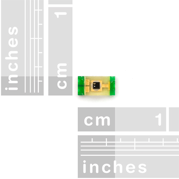
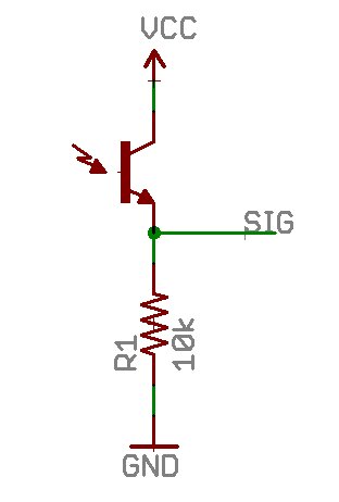
This is a small ambient light sensor that acts as an NPN transistor. The more the sensor is exposed to light, the stronger the base bias. Simple to use! Simple breakout board available below.
Ambient Light Sensor - TEMT6000x01 Product Help and Resources
EL Wire Light-Up Dog Harness
October 30, 2015
Learn how to create a light-up dog harness using EL wire for when you need to take your four-legged friend for a walk in the dark.
TEMT6000 Ambient Light Sensor Hookup Guide
October 26, 2016
Bring the ability to detect light levels to any project with the SparkFun TEMT6000 Ambient Light Sensor Breakout.
Core Skill: Soldering
This skill defines how difficult the soldering is on a particular product. It might be a couple simple solder joints, or require special reflow tools.
Skill Level: Competent - You will encounter surface mount components and basic SMD soldering techniques are required.
See all skill levels
Core Skill: Programming
If a board needs code or communicates somehow, you're going to need to know how to program or interface with it. The programming skill is all about communication and code.
Skill Level: Noob - Programming will be limited to basic drag and drop interfaces like ModKit or Scratch. You won't be writing code, but you will still need to understand some basics of interfacing with hardware. If you?re just using a sensor, it's output is analog.
See all skill levels
Core Skill: Electrical Prototyping
If it requires power, you need to know how much, what all the pins do, and how to hook it up. You may need to reference datasheets, schematics, and know the ins and outs of electronics.
Skill Level: Competent - You will be required to reference a datasheet or schematic to know how to use a component. Your knowledge of a datasheet will only require basic features like power requirements, pinouts, or communications type. Also, you may need a power supply that?s greater than 12V or more than 1A worth of current.
See all skill levels
Comments
Looking for answers to technical questions?
We welcome your comments and suggestions below. However, if you are looking for solutions to technical questions please see our Technical Assistance page.
Customer Reviews
No reviews yet.
Would I be correct in saying that the Base is not connected to anything?
I've bought 4-5 of these for use in our lab, one is mounted on our sun tracker controller, and works great (using it with 4 photo-resistors to give the sun's relative location and irradiance.) but the last 3 have been duds.. The diode reads either as on open or shorted circuit. We hook them up to arduino's, so even a crossed wire hook up should only be 5V, which I don't think can burn out a photodiode. Any idea what is happening? Here are pics of the good and bad sensor (https://plus.google.com/107935709908498477582/posts/5fXwMVz4Yfn ). Could overheating the board when soldering do this?
I usually solder @ 358°C, 3-4 seconds on the to-be-joined metals, then apply a solder bridge, then solder the other bit to join to the bridge (4-6 seconds total). But according to the datasheet these have a MAX time of 3 seconds with a MAX temp of 260°C. Which means I would probably destroy everyone I soldered using my 'norm.' If you're like me then yes you probably overheated them...
tl;dr: Solder it in under 3 seconds and under 260°C
I was wondering how bad temperature would affect this sensor. We are planning on using them to determine the brightness of the sunlight on livestock. We are in the south and the heat can get rather extreme. Also, I only have 3.3 volts available, will this work with a lower voltage? Thanks, Brian
I'd use a temperature-compensated light-to-frequency converter like the TSL235R instead. It works fine on 3.3V too.
And yes, it will work fine at 3.3V.
Hello, the temt6000 is no longer produced by Vishay. Are you going to replace it with the new TEMT6000X01?
I checked and the part we're selling is the TEMT6000X01. Thanks for pointing this out, I'll get the new datasheet posted. (In the meantime, the datasheet can be found at: http://www.vishay.com/docs/81579/temt6000.pdf.)
Thanks so much!
Have a look at the datasheet directly from Vishay;
http://www.vishay.com/docs/81579/temt6000.pdf
Page 491 (don't worry, there's not actually that many pages in the document) has the current vs ambient temperature graphs you're looking for.
Thanks so much. So, on a given day it could be 70 in the morning and 98 in the afternoon. Would I need to log temperature and do some sort of correction for the light measurement to be the same through out the day?
In that chart, the relative output is basically a multiplier, with 1.0 set to about 77F (25C).
For 70F, the multiplier is about 0.94.
For 98F, the multiplier is about 1.18.
Whether that is of actual concern depends on your application, though.
Thanks so much again for your help. This would be used for livestock behavior research. We have Kinetamaps that we are using for location and accelerometer to count steps and bites. We would like to add the ability to log the brightness of the sun. Basically, we are trying to determine at what sun intensity an animal seeks shade. So we would need the sensor to accurately record the brightness of the sun across all temperatures so that data recorded in the dead of winter is comparable to data that is recorded in the height of summer. Do you think this type of sensor is the right choice? If so, should I record temperature and use the multipliers to compensate for temperature?
Yes, you would have to record temperature as well ( which I'm guessing you may already be recording? ) and compensate accordingly.
However, I'm not sure this sensor is right for the purpose. The datasheet doesn't really give the information I was looking for, namely the range of the sensor. However, the lux vs current graph only goes up to 1,000 lux. Broad daylight (not even counting the sun) is well into the tens of thousands of lux. On the other hand, the datasheet also mentions a maximum collector current of 20mA which, if the graph continues linearly, should be adequate even for full sunlight.
So this might be a question for the forums - get a few more eyes on it. If nothing else, I'm sure there will be alternatives suggested :)
Is it possible to detect colors(red|blue) with this sensor?
Sort of, but probably not in a way you'd like. If you look at the second page of the datasheet, you'll see a graph relating responsivity and wavelength. Assuming red == 700nm and blue == 450nm, you're looking at ~0.8 and 0.6 relative responsivity.
Whether that's enough to be discernible by your control system is up to you and your design.
obviously that is not possible as it heavily depends on the luminance of the object. i suggest buying 3, and buying 3 markers, a red blue and green marker. Those make sure only resp. red blue and green light passes through. jippy problem solved.
Here's a very direct way of doing pulse oximetry with TEMT6000 by measuring the amount of light from a red LED that passes through human body:
http://flipthatbit.net/2011/04/simple-pulsoximeter/
TEMT6000X01 product information
http://www.vishay.com/product?docid=81579