- Home
- Product Categories
- Kits
- Tri-Color LED Breakout Kit


Tri-Color LED Breakout Kit
Replacement:KIT-11588. We have revised the board in this kit. This page is for reference only.
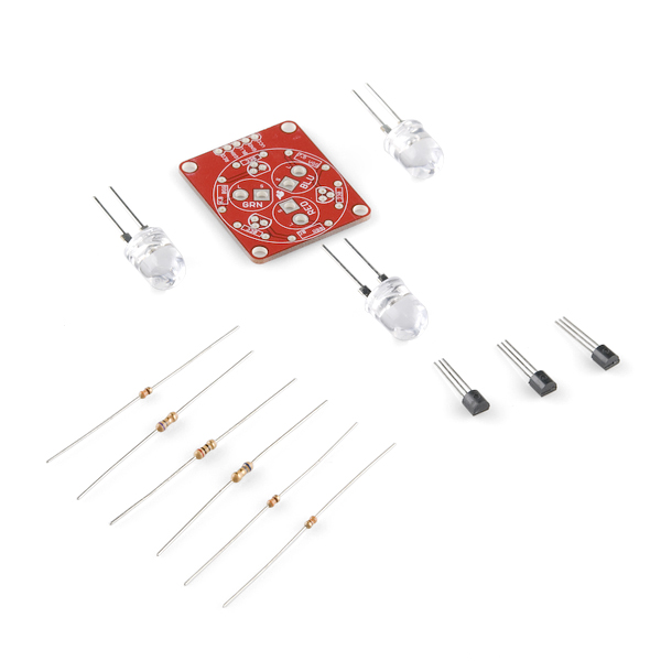
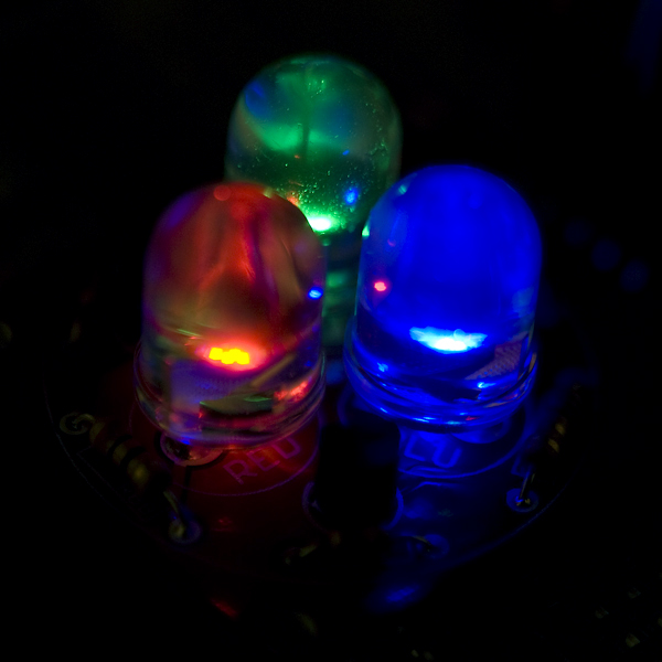
This is a simple kit that allows the use of very large, very bright, 10mm red/green/blue LEDs. We cannot begin to describe how bright these are when fully illuminated! After assembling the kit, you can control the LEDs via the RGB pins. By pulse-width-modulating the pins any color can be created by mixing different amounts of red, green, and blue. Running from a 5V source, these LEDs are painfully bright.
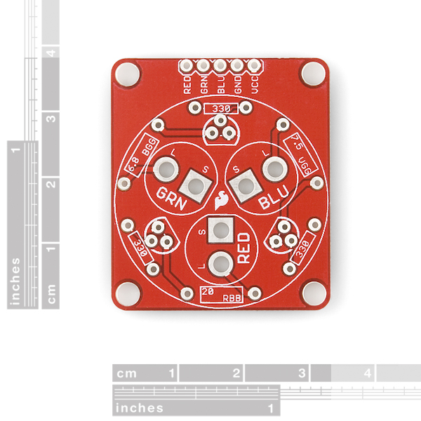
This board is designed to run off 5V and put the max 80mA through each LED. Be sure to pay attention to the different resistor values and LED colors. Each is marked clearly on the PCB. You will need a coin cell battery or multimeter to briefly illuminate the LEDs to tell what color they are before assembly.
Note: Although this board is pictured with pin headers, pin headers are not included in this kit. If you need some, however, they can be found in the related items below.
- Schematic
- [Eagle Files](http://www.sparkfun.com/datasheets/Kits/Tri-color LED Breakout-v12.zip)
- Datasheet (Blue 10mm LED)
- Datasheet (Red 10mm LED)
- Datasheet (Green 10mm LED)
- Example Code
- Quickstart Guide
Comments
Looking for answers to technical questions?
We welcome your comments and suggestions below. However, if you are looking for solutions to technical questions please see our Technical Assistance page.
Customer Reviews
No reviews yet.
Just found out about this, from the news of the retail packaging. I'm curious... had you guys considered putting the load on the collector side? With the LED and drop resistor on the emitter side, the delivered current will be dependent on the voltage from your microcontroller. With a 5V micro, you'd have 5V at the base, ~4.3V at the emitter. But with a 3.3V micro, you'd only have ~2.6V at the base, which wouldn't even turn on the Blue or Green LEDs. But if the LED and drop resistor were on the collector side, the current would be (more or less) independent of driving voltage.
I made a very similar board for Halloween lighting, and posted it to batchpcb a few months ago. I did quite a bit of testing using 10mm 1W LEDs. One thing you may find, is that the Vf changes as the LEDs warm up. This may be causing some of the deviation you were seeing
Dah! My bad. This is what happens when you let a CEO layout a circuit. The NPNs should be on the low side. I'll start a fix (https://github.com/sparkfun/Tri-Color_Breakout). For now, v1.2 of the board works well enough. We'll get v1.3 tested and posted soon!
Yup, makes sense to me.
I knew I'd seen this problem before... the Max Power IR kit and new version of said kit. :)
Isn't grounded emitter and load on the collector the recommended form? http://www.rason.org/Projects/transwit/transwit.htm http://www.kpsec.freeuk.com/trancirc.htm and http://en.wikipedia.org/wiki/Transistor all seem to think so.
So on this board, we'd need to swap CE legs of the transistors (maybe mount them on the back side of the board) and reverse the LEDs and reverse the usage of pins 4,5 of JP6 (vcc and ground). I guess you could build the entire board on the back side... The only issue for me would be remembering that Vcc and GND are reversed on JP6.
Oh, might also need to tweak the LED resistor values... I wonder if some of Nate's variance with calculated values is because of emitter loading? (the emitter being offset from ground by 2v-4v)
So if you flip the whole circuit to the back and reverse the LEDs and power pins it looks right. What would the resistors have to be changed to?
Could you swap in PNP transistors for the NPN and then recalculate the resistor values? I guess that would flip the "bittness" so that high on the pin turned off the LED and low on the pin turned on the LED but that's a simple software fix...
Yes - just saw this too (linked from new retail package). This isn't a properly designed LED driver.
To drive an LED with a transistor, you use an NPN as a low-side switch (emitter grounded), or a PNP as a high-side switch (emitter to Vcc).
What this board does is use an NPN as a high-side switch. This is do-able, but not as shown in this design. You typically need >0.7 V across the base-emitter to fully saturate an NPN; this means you need >5V on the base for this to function properly.
For this reason, NPN's (and N-channel mosfets) aren't used as a high-side switch (without proper base/gate drive). As others' pointed out, this why you need to play with the resistor values in the lab to get these to light properly.
While there are plenty of good tutorials on using transistors as switches (high-side, low-side), unfortunately, this design keeps propagating. In addition to this card, the same circuit is also shown throughout the Make Electronics book, as well as other designs on the web.
While technically it works (assuming RED/GRN/BLU inputs are >>Vf of diode), it's not the correct way to use an NPN as a switch.
The LEDs are very bright. The red in particular is searing.
Yeah I love SparkFun but you guys are right, this design is all wrong. My calculator told me that the LEDs would go up in smoke with the resistor values shown; Then I realized that they were using an NPN as a high side switch. These transistors as shown can never saturate, that's why the resistors are so small in series with the LEDs, They should be using the good old 2N2222 as a low side switch. The base resistors could be around 3.3K since the 2N2222 has more DC current gain, and the dropping resistors could be calculated assuming a VCE sat of 0.2 VDC. This would be much simpler, and transistors with different current gains could be substituted without having to recalculate the resistors to avoid blowing up the LEDs.
Man, these are hyper-bright. The three LEDs have a combined output of 30 to 40 candela, making this array on the order of 100x the brightness of a generic 5mm LED. If you look directly at them for even a moment, you will see spots for quite a while. They have a fairly narrow viewing angle (30° according to the data sheet) so they're safe to look at from the side.
I may try diffusing mine with a gentle sandpaper rub...
used a watch battery to test, and was only able to get the red LED to light up....
:( I see that it is dependent on a lower voltage though. hopefully that is the only reason?
What is the voltage of the Battery?
I made a small Arduino sketch for this nice little kit, which fades randomly all three LEDs. I put some comments in it, so that the code could be better understood by Arduino starters. Maybe it's not the best code, but it works ;)
Sparkfun Tri-Color-Breakout-RBG
Feedback would be nice.
This worked out great! Thanks for sharing.
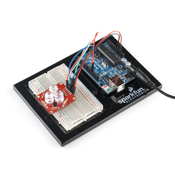
I have published some code for interactive RGB mixing with this kit. The hardware requirements are this kit (KIT-10111) and an Arduino. The processing code takes mouse input to control the RGB mix over the serial connection with the Arduino. More details, video, and code are posted at The Daily Photon, RGB Mixing
I would normally scoff at that $9/3LED price, but having priced those things out myself, it's pretty comparable you'd pay via other methods. Really puts a damper on mass deployment of them though.
Thanks for the feedback on the price! The 10mm LEDs have 4 dies each and are a bit pricey even in bulk. For a single setup, this kit is great. For large scale many RGB, it's perhaps better to go with strip LED lighting or a fully custom solution.
How are the current limiting resistor values (r1,r2 and r3) calculated? The red LED has vf ~2.2 so it seems like r1 should be (5-2.2)v / 0.08a = 35 ohms and r2=r3= (5-3.2)v / 0.08a = 22.5 ohms. What am i missing?
Mkay - I randomly selected a bag of parts and assembled a test unit. This is what I measured:
VCC of power supply: 5.04V
Red current: 82.3mA
Green: 69.3mA
Blue: 73.3mA
So red is just a little bit high, but in general the LEDs are pushed to near their max, but not dangerously over. Thanks for keeping me on my toes! And now I'm seeing spots. Jeesh these are bright.
Great question trl - and you are calculating things correctly. On paper V=IR works great. Then you actually go to measure the current and things get funky. I laid out the board wanting to drive the LEDs at or near their max of 80mA. Calculations said one thing, and under actual testing I had to lower the resistors until the LEDs were in the 70mA range. Reed makes a great point that the 2904 should drop only 0.3V. I'll double check that the LEDs are not going over 80mA.
In transistors there is a specification called "Collector-Emitter Saturation Voltage" for this transistor(2N3904) it is about 0.3V so your formula would be more like: (5-(2.2+.3))/0.08 = 31.25
However you are also using the forward current, sparkfun is using the "Peak forward Current" of 120mA. (2.2+.3))/0.120 = 20.8 Ohms
The suggested current for this diode is 65-75mA. I can only imagine these are running outside of spec. going full-duty cycle at peak current.
ive been hoping to see a non-luxeon replacement for the rgb-blaster.
they look great for toying around with.