- Home
- Product Categories
- Sensors
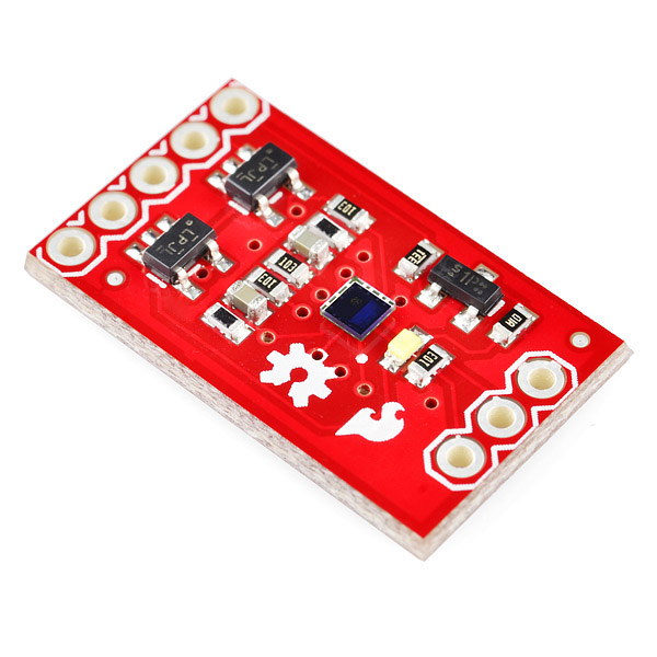
- Color Light Sensor Evaluation Board

Color Light Sensor Evaluation Board
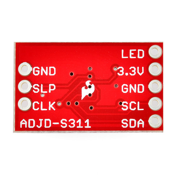
Replacement: None. The ADJD-S311 is no longer in production so we can no longer carry this sensor in our catalog. This page is for reference only.
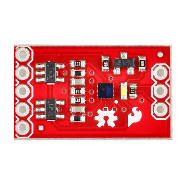
The ADJD-S311-CR999 is a great little color light sensor. In fact, it's so little that it can be pretty difficult to play with, so we made this evaluation board! It provides all the necessary support circuitry to discern the smallest differences between visible colors.
Replaces:SEN-08663
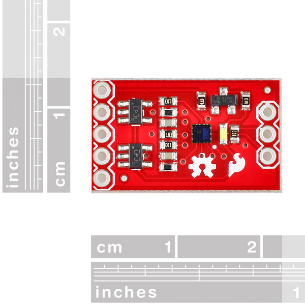
- 21.6x12.7mm (0.85x0.50")
Color Light Sensor Evaluation Board Product Help and Resources
Core Skill: Soldering
This skill defines how difficult the soldering is on a particular product. It might be a couple simple solder joints, or require special reflow tools.
Skill Level: Noob - Some basic soldering is required, but it is limited to a just a few pins, basic through-hole soldering, and couple (if any) polarized components. A basic soldering iron is all you should need.
See all skill levels
Core Skill: Programming
If a board needs code or communicates somehow, you're going to need to know how to program or interface with it. The programming skill is all about communication and code.
Skill Level: Rookie - You will need a better fundamental understand of what code is, and how it works. You will be using beginner-level software and development tools like Arduino. You will be dealing directly with code, but numerous examples and libraries are available. Sensors or shields will communicate with serial or TTL.
See all skill levels
Core Skill: Electrical Prototyping
If it requires power, you need to know how much, what all the pins do, and how to hook it up. You may need to reference datasheets, schematics, and know the ins and outs of electronics.
Skill Level: Noob - You don't need to reference a datasheet, but you will need to know basic power requirements.
See all skill levels
Comments
Looking for answers to technical questions?
We welcome your comments and suggestions below. However, if you are looking for solutions to technical questions please see our Technical Assistance page.
Customer Reviews
No reviews yet.
The ADJD-S371-CR999 replaces the ADJD-S371-CR999 which was a great sensor. However, both aren't so easy to program, due to multiple settings, including capacitor and timer, offset and white balance.
Please find the Arduino library I developed, as well as details on calibration and encasing.
Enjoy!
possible snag here -- we want to run more than one of these on a single Arduino -- is it true that the provided software library is "bolted" to A4 and A5, only? Eg. you can't tell it what pins it's tied to?
I admit i've only glanced at the .cpp and .h files, but the example Arduino code is a bit foreboding:
The lib code isn't passed the pin #'s as an argument anywhere, so it seems that this is in fact the case. please tell me this ain't so?
(I guess i'll have to write my own driver for it.)
The pins are fixed on an Arduino, but beyond that it looks like - and somebody might correct me here - the device itself (the ADJD-S311 light sensor) has a fixed serial bus address; 0x74. So if you wanted to communicate with more than one, you wouldn't be able to do so on the same bus.
yeah, it's odd. i read the datasheet, the slave addr fixed at 0x74 is too bad. however, for a smallish number of sensors, paralleling all the SDAs and assigning each SCL to an arduino digital pin would get you a dozen or so, 'good enough' for most projects. Alas, SCL and SDA are not parameterized. I realize it's a "demo driver" but it's a shame (and odd) that it's hardwired to A4 and A5 (unless there's ATmega two-wire proto hardware support on those pins, but even so...). Oh well. And thanks for the reply.
SCL and SDA are not parameterized because they are a hardware I2C function of the micro-controller. You could bit-bang the I2C interface on other pins in software.
The ADJD-S311 does have a sleep pin. You should be able to connect more than one on the same I2C bus and talk to them individually by putting all of them except the one you are talking to sleep.
Does it come with the tiny sensor itself?
Yes
I wish I had seen this post a couple weeks ago. I ordered a couple boards about 2 weeks ago and I also ordered a couple timy sensors to go with them. Now I have two boards and two tiny sensors. The boards are what I was looking for, but the sensors are useless now since I can't connect anything to them.
Is arm code missing header file for device, and makefile?
there is no need to define pins, just download this http://code.bildr.org/download/965.zip
then copy the "ADJDS311" file to Arduino IDE Library
Can you help me to find out the maximum conversion time of this card please?
I just got this working with an Atmega324 - will post some code soon.
One annoyance - you can only read one register at a time. If you try:
i2cstart
i2csendaddress //write address
i2csendbyte //0x40, for instance
i2cstart
i2csendaddress //read address
i2creadack // get byte 0x40
i2creadnack //get byte 0x41
i2cstop
You will only get the first byte. The datasheet does only give an example for a single byte read, but it means that you can't read out all the colour intensity registers in one go. Still, pretty nifty little chip!
When will this be back in stock?
I discovered, while soldering pins to this board, that the sensor has a bluish optical coating on it that can be damaged if you are careless.
when i calibrate it give value above 1000, and i did everything correct can anyone help me?
I am only starting to play with these myself, but you may be giving it too large a time slot.
It's like a photo film. The capacitance is how sensitive it is -- the lower the capacitance, the more sensitive it is. The integration time is the exposure time. So, make it a less sensitive 'film' by giving it more capacitance, and give it less exposure by reducing the time slot, and you should get lower values.
Dear all, I want to know that is there any efficient way to reduce the pins if I need to deal with more than 2 color sensor boards but only with one Arduino at the same time? Thanks a lot
the difficulty is that the i2c address is hard coded the same on the sensor itself. it's been suggested that you could use the sleep pin to put them all to sleep except the one you want to read. you can only read one at a time over i2c anyway. drawback is that it requires a digital pin for each sensor, or maybe an i2c port multiplier.
other option might be to use one of the software i2c libraries that bitbang the protocol instead of using the hardware i2c interface..
You and several dozen others on this page. It appears not.
If you plan to buy this take note...the distance between the 3 pin header and the 5 pin header is NOT a multiple of 0.1". So this won't quite fit in a standard breadboard. You'll have to either squeeze the pins together or pull them apart but you won't be able to get it to sit flush.
Honestly this is a bit baffling. Sparkfun, this isn't the first product I've ordered that has off-grid headers that could have easily been made standard 0.1". What gives? I can't think of a possible reason for it on this product.
will this break if you put 5v on the 3.3 volt line instead of 3.3V? i hope not :$ thanks
Can I use this with a BASYS 2 board?
I am trying to work with this sensor and an Arduino Uno, and I am using the example code, and it is just going to where it says that it is calibrating, and stays there. I have it wired directly to the arduino the way the program says, is there some problem with the program, or am have I done something wrong?
I am having the same problem, did you ever find a solution?
Same issue; stuck at "Calibrating...this may take a moment" Using an Arduino Uno.
My sensor board LED is lighting up and blinking during the never ending calibrartion.
...have had some mixed results. Succeeds only about 1:10 times :( Placed comments in the calibration functions and it seems several of them cab halt the process. Only way to restart is to reset the Arduino. What a pain!
UPDATE: Nevermind, my fault. Had it wired wrong. See the tutorial... http://bildr.org/2011/01/adjd-s371-tutorial/
I test both code from Bildr and the code from SF (Jim Lindblom) and both work on the Arduino Uno R3. The first time I tried with a original UNO it did not work, it was stuck on the "Init" using Bildr code. I then tried with the UNO R3 and everything work perfectly. Now I am playing with Jim code and trying to get the RGB led to light up when I press "l". Everything seems to work fine except that.
I have a bunch of 5V devices on an Arduino I2C bus. Can I connect the Color Sensor's 3.3V to 3.3V source and then connect the SCL and SDA to an I2C bus where the other devices are 5V. I'm sure the answer is "obviously yes" or "obviously no" :-). If you could explain the answer also, that would be great.
the answer is "it depends". I've used a 5V arduino as a i2c slave with a 3.3v beaglebone without issue. it works because the beaglebone's pullups are strong enough to to handle the small current needed for i2c. I don't know if this is true of this sensor.
Is there any way to change the I2C address for the ADJD-S311? I would also like to use two of these boards at the same time but don't know that it's possible...
With the hardcoded I2C address value of 0x74 is it possible to have more than one of these board on the same I2C bus?
No, you can not have two or more devices responding to the same address or you will have bus contention. That is, if they are all powered up at the same time.
On another note, not sure why one would power this device from 2.5V, this would mean that your I2C interface must run from the same supply voltage. Good luck with that!! This device is capable of having a 3.3V supply. There is nothing that says you can not have different A & D supply voltages, as long as they are within the spec's.
Has anybody tried interfacing using an mbed? I thought I would be able to use the ARM code but I can't find the headers files being referenced.
I dont now how to use this colorsensor. I want to read regulary RGBvalues but this sensor cannot! This problem is colorlightsensor? or sourcecode? now, I using ADJD-311 colorlightsensor. but values very irregulary!! I really want to make regulary RGB data values!! but so very hard!! please anybody help me!! I researching this project but difficult. If anybody ok, please send my e-mail. send regulary RGBvaules. rosshild21@gmail.com here my e-mail source code and explain please!! I waiting….. thanks.
I notice that there are two LDO's on the board. Has anone tested the IC by using only one. What would happen if i join the analog supply and the digital supply to the same bus?
Wonky things happen when you connect Avdd and Dvdds to the same bus directly, keep your analog and digital grounds separate too, until all the way back at the power supply or board power in point. Just good practice to save you headaches.
Great! There was definitely demand for a breakout board, as the comments in the sensor's product page suggest :) Too bad you didn't just pick up on Paradoxial's board, though.
Those looking for a rather simpler sensor might want to check out the Kingbright KPS-5130PD7C. It's an analog device (i.e. it'll eat up your ADCs) with plenty of light catching area in a larger package that's easier to handle (no need for a breakout). No built-in illuminator, though.
Unfortunately they're only great for doing some basic color testing without a calibrated colorimeter to test against if you really wanted to know if the color you're sensing is "Geraldine", and not "Japonica" or "Sunglo".
Since this runs off 2.5v minimum why not simply use a 2.5v regulator. Im sure it would be better than 2x 2.8V regulators
I think they're trying to isolate the analog and digital supplies by providing separate regulators for each... See the data sheet.
Wow. This seems strangely wrong somehow.
It appears that the sensor itself appears in the related products for the board, but the board does not show up in the sensor's related products.