- Home
- Product Categories
- Other LEDs
- LED Matrix - Tri Color - Large


LED Matrix - Tri Color - Large
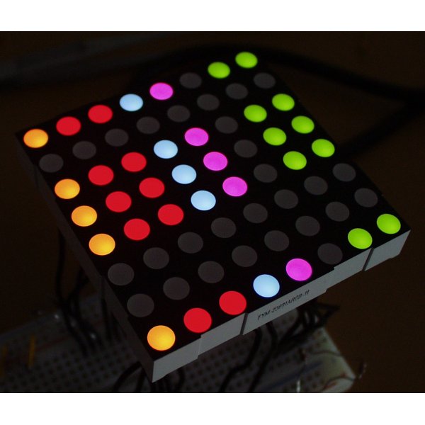
Triple Color LED Matrix! This large matrix has 64 Red, 64 Green, and 64 Blue individual LEDs built into one common cathode housing. It's a monster to control, but just imagine what kind of colors you could produce by mixing!
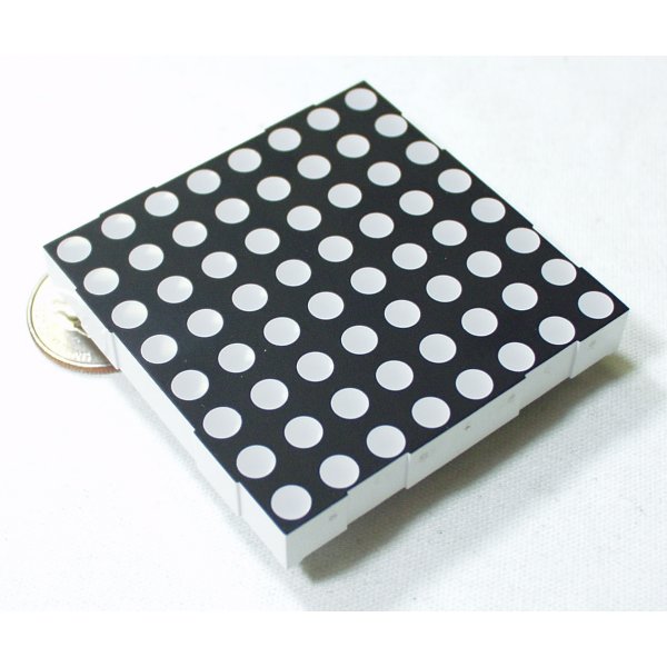
These are the new, readily available units that just arrived. Unit comes with a black finish and opaque LED lenses.
- 0.33x2.38x2.38"
LED Matrix - Tri Color - Large Product Help and Resources
Core Skill: Electrical Prototyping
If it requires power, you need to know how much, what all the pins do, and how to hook it up. You may need to reference datasheets, schematics, and know the ins and outs of electronics.
Skill Level: Competent - You will be required to reference a datasheet or schematic to know how to use a component. Your knowledge of a datasheet will only require basic features like power requirements, pinouts, or communications type. Also, you may need a power supply that?s greater than 12V or more than 1A worth of current.
See all skill levels
Comments
Looking for answers to technical questions?
We welcome your comments and suggestions below. However, if you are looking for solutions to technical questions please see our Technical Assistance page.
Customer Reviews
No reviews yet.
Hi, out of curiosity, why did you retire this product?
The popular WS1812 and other addressable LEDs have pretty much replaced these in the market. With their fairly cheap price and addressability more and more people are using those. So probably a combination of seeing this as older technology on its way to relative obscurity and low sales caused these to be retired.
Is this thing really static sensitive like it says in the datasheet? Isn't it just a bunch of LEDs?
I bought this a while back. I took it back out again and I don't understand how to use it. I looked at the datasheet, found a few blog posts and still don't get it. Can anyway let me know which way up is it and what pin does what? Thanks for your help in advance, I appreciate it.
If you really want a matrix of LEDs with opaque lenses, just buy 64 of these and save a bunch of money.
lol
So, does anyone have 23001.60$USD to buy 768 of those things to make a giant Nintendo DS display (256 x 192 pixels)?
It's only $18,401.28.
Only $18,401.28. Mere pocket change.
Loads of fun, and easy to use with Arduino. I wrote a tutorial about it here: http://bit.ly/9o3dso
I wrote a driver for this using arduino and shift registers (optional), code is here: http://marc.merlins.org/perso/blog/cat/arduino/post_2015-01-06_Driver-for-direct-driving-single-to-3-color-LED-Matrices-with-software-PWM.html Video demo: https://www.youtube.com/watch?v=tKCOY1tTtM4
Posted a tutorial showing how to control these with some shift registers: http://learnpic32.blogspot.com/2014/06/controlling-rgb-led-matrix-with-shift.html
I had a look at that code, and wrote another one that's a bit more efficient (binary code emulation for PWM) and supports using a higher level library to write to the matrix: Adadfruit::GFX. See https://github.com/marcmerlin/LED-Matrix
Would this board be compatible with this driver? http://www.seeedstudio.com/depot/rainbowduino-led-driver-platform-atmega-328-p-371.html
Not directly. This is a Common Cathode display - the Rainbowduino ATMega328p board is a Common Anode driver. While it's technically possible to build a board that inverts the logic appropriately, you're much better off finding a Common Anode display - or looking for a Common Cathode driver.
My Infinity Mirror senses are tingling
Why are all the best drivers common anode (TLC5940) and all the best LEDs (this one, COM-10595, COM-10390) common-cathode? :( :( Where's the sweet spot? What's the best way to drive those common-cathode LEDs with PWM?
I wish I'd got this instead of the cheap one on ebay. There is great value in diffusive lenses, which mine does not have.
Great display! Just got mine in the mail. Don't make my mistake though - I accidentally touched +5v to the wrong side of a resistor. :( Now a red LED is way dimmer than the rest. Is there any way I can get this replaced? (even use a discounted price maybe?) I'm 14 and I don't have much money to spend on electronics.
unfortunately there's no way to actually fix this, sorry.
Oh well, thanks anyways. At least the rest of it works.
I'll see if I can dig one up. I might have one sitting around in one of my boxes.
Thanks a lot for your help!
I actually think I have one. Is your contact information in your account correct? I can send one out to you.
Yes it is, thanks so much! :D
I'll try to remember to send it out tomorrow. Good luck!
It's in the mail.
[Thanks a lot, it works! Click here :P] (http://futureinventionstech.com/videos/Blank.html)
The link didn't show as I intended, but it's a picture to show my thanks for your awesome customer support.
You're welcome ;-)
When will they re-stock on these? These looks fun to play around with on the Arduino! :D
I purchased this but after much searching was unable to find any LED driver for use with this common cathode display. I ended up using a much cheaper, and lower quality, common anode display I found on ebay. The nice thing about the drivers I ended up using (TLC5940) was the current could be set with a single resistor and they supported PWM which was what I was looking for. While you could still use those with their PWM to switch transistors to drive the anodes it's not really an elegant solution and the TLC5940's minimum current is 5mA, below which they operate somewhat unpredictably. I've seen a common anode version of this display on ebay and I'd recommend SparkFun stock that instead if possible. Anyway, this display inspired my design project at UCSD and here's a video of what can be done with them. I made a spectrum analyzer and spectrogram out of the display using the MSGEQ7 available here on SparkFun. Micro-controller was an Arduino UNO: Graphic Audio Analyzer
Just FYI, I found the AS1107 common-cathode IC to drive up to 64 LED's. This doesn't have PWM, which is a downer for RGB Led's, but it works nicely with simple on/off control. Thought I'd share anyway :)
All controllers can do PWM, you just have to turn them on and off quickly in software.
I would also love to see a common anode version of this display.
I like this. I like this a lot.
do these work like a GLIP
See http://batchpcb.com/index.php/Products/54792 (edited!) for a reasonably compact PCB design to control this matrix with the microcontroller of your choice, 5v or 3.3v power, and 4 data lines (serial clock, register clock, master reset, and data in.) Data and power in/out are provided on 2x5 IDC headers. The board is chainable so you can create a wider display with multiple LED matrices.
Blog w/pics, video of this board (and a Parallax Propeller project to make it into a scrolling text display/clock at http://forums.parallax.com/entry.php?118-My-expandable-full-RGB-blinky-LED-matrix-with-color-fading-scrolling-text.
Is that PCB design still around somewhere? The link's broken.
I'm interested in building custom controller(s) for a 4-panel display, and it'd be handy to have some kind of starting point.
Sorry: try this link:
http://www.batchpcb.com/index.php/Products/54792
The board is still available. (This is a revised version with mounting holes and reversed header layout. See the notes for the project on the product page on BatchPCB.)
How about some schematics? :)
Has anybody found a simple way of driving these with a MAX6960?
It's PERFECT for driving the R and G parts of the matrix with a ton of cool features, but it requires extra high and low side drivers to make the B part work.
I can't imagine sign mfgrs add another hundred parts or so per 8x8 matrix... is there a simpler way to drive the Blue matrix?
The 6960 is an incredible chip... I'd love to drive a bunch of these with them.
Any help?
Thanks!
Datasheet shows one row of 15 pins, but the part has 32 pins! Also the brightness drop of 17% after 1000 hours is not so great.
Here is the Eagle library for this one: http://insidegadgets.wordpress.com/eagle-libraries/
Please do a 1:1 print out to confirm and let me know, I followed the data sheet so let me know if the pins are actually for the correct red/green/blue LEDs.
http://en.wikipedia.org/wiki/Kelly_green#Kelly_green
Er, exactly what colour is "Kelly" (from the datasheet)? I can't even figure it out from the context. Maybe I'm "Kelly colourblind"? :)
It appears, from the picture and the reports of success in using this device, that there's an error in the description. If the LED lenses were "opaque", no light could get through them. They appear to be "translucent" and "diffusive".
Eric
You mean TLC5940. I knew of the part but could not find the datasheet on TI's website.
http://focus.ti.com/lit/ds/symlink/tlc5940.pdf
They have some apnotes (see bottom of page)
http://focus.ti.com/docs/prod/folders/print/tlc5940.html
I spent some time looking at the TLC594X series LED drivers, and they seem to have a lot of potential...but they all operate as current-sinks instead of current-sources.
I'm still new to this, but it seems to me that these wouldn't be usable for a common cathode display like this (you'd need a common-anode display).
Does this sound right? Is there an easy way to compensate for this that I'm missing?
I would recommend using a PWM/constant current driver such as a TLC5490 to handle the dimming. This frees up your micro to do a lot of other stuff. You typically just need to shift in the brightness levels once per row (using SPI). It's easy to acheive 30 fps and 24 bit color this way.
The pin-out is just fine, use your DMM in diode mode to identify pin 1. The color intensity varies noticeably between the blue LEDs. Timing constraints with a typical MCU will limit you to about 512 colors. Wish the price was more modest.
late reply, but if you shop around, you can get these for MUCH cheaper.. I just bought 30 of the bi color 8x8's for 99 cents each...
The price is probably a bit excessive.
On mine, the color and intensity are perfectly uniform on all the colors. Are you using current limiting resistors on the cathodes?
An odd thing I almost missed on the datasheet - the green and blue LEDs are 3.3V, but the red ones are 2.0V (2.2max!). You'll need to put a voltage divider on the red pins.
You do NOT need a voltage divider on the red pins. 2.0V is the voltage drop, not the allowed voltage. You can run these off of 12V as long as you use appropriate current limiting resisitors.
It's very common for red LEDs to have a lower voltage drop than green and blue LEDs.
The current limiting resistors should go on the anode side of the LEDs. The red LEDs will need a slightly higher value of resistor than the green and blue LEDs.
Let's assume, you're using 5V to drive this. For the red LED you subtract 2.0V from the 5V to find the voltage drop across the resistor. This give us a 3.0V drop across the resistor. Since the current should be limited to 20mA we can use Ohm's Law to calculate the resistor value. R = V/I = 3.0V/0.020A = 150 Ohms.
The green and blue LEDs would have (5.0V - 3.3V)/0.20A = 85 Ohm resistors.
You could use lower resistor values if you're multiplexing the LEDs(since each LED would only be on for a short duration of time).
What types of current limiting resistors are you using?
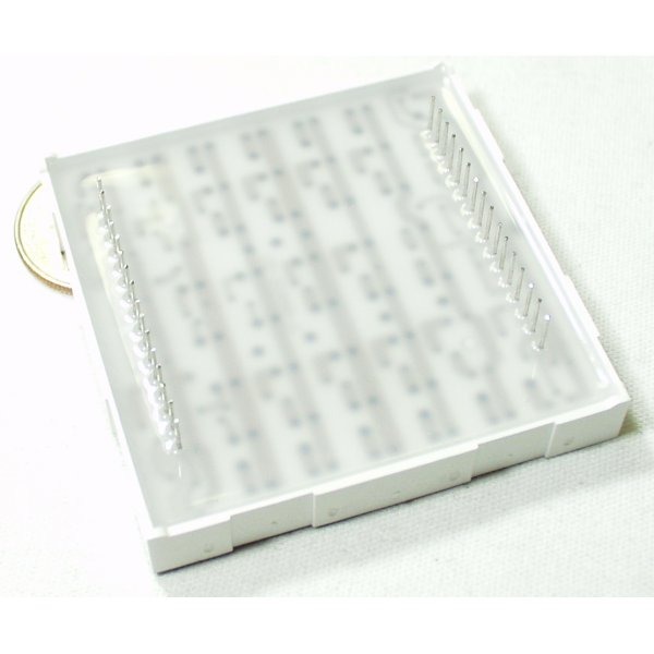
The datasheet pin numbers don't seem to match the grid. Does anyone have a proper pinout for this?
Flip it pins-up. Orient the serial number rightside-up. Pin #1 is on the bottom right. Pin #17 is on the top-left.