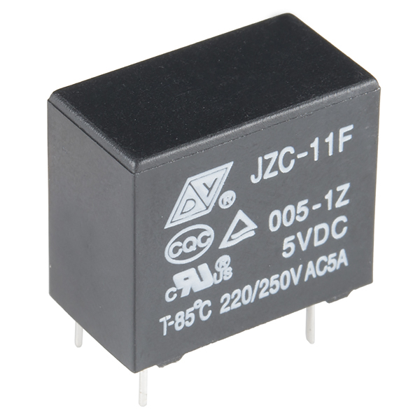
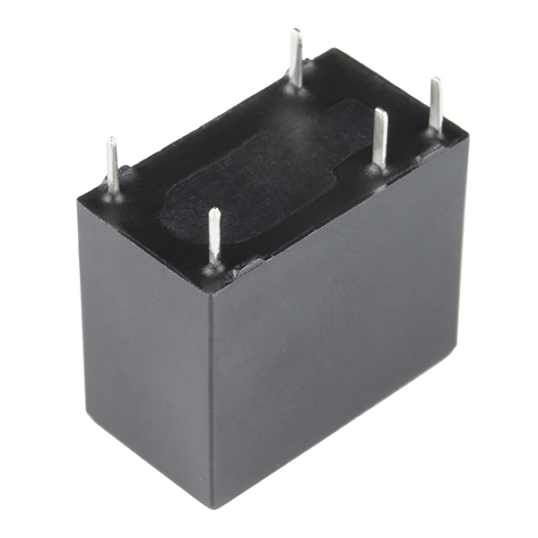
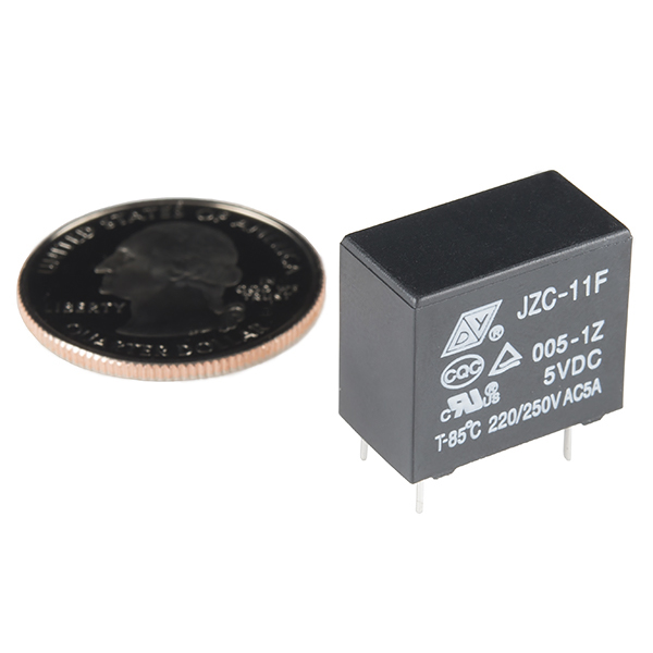
These are high quality Single Pole - Double Throw (SPDT) sealed relays. Use them to switch high voltage, and/or high current devices.
This relay's coil is rated up to 5VDC, with a minimum switching voltage of 5V. The contacts are rated up to 5A (@250VAC, 30VDC).
- Contact Rating (at Resistive Load):
- 5A 250VAC
- 5A 30VDC
- Max. Switching Voltage: 250VAC, 30VDC
- Max. Operating Power: 1250VA
- Max. Switching current: 5A
- Min. Switching Load: 10mA 5VDC
- Coil Rated Voltage: 5VDC
- Coil Rated Current: 90mA
- Pick-up Voltage: 3.75VDC(75%Max.of nominal voltage)
- Drop-out Voltage: 0.25V(5%Min. of nominal voltage)
- Coil Resistance: 56Ω±10%(at 20℃)
- Contact Resistance: Max. 100mΩ(initial)
- Insulation Resistance: Min. 100MΩ at 500VDC
- Dielectric Strength:
- Between Coil & Contact: 3000VAC 50 HZ/60 HZ (1 minute)
- Between Contacts: 750VAC 50 HZ/60 HZ (1 minute)
- Operate Time: Max. 20mSec.
- Release Time: Max. 10mSec.
- Ambient Temperature: -40℃~+85℃
- Vibration Resistance (Endurance): 1.5mm D.A. 10-55HZ
- Shock Resistance: Min. 10G Unerror
- Mechanical Life: 10,000,000 Operations (no load)
- Electrical Life: 100,000 Operations (at rated load)
- Weight: Approx. 4g
Relay SPDT Sealed Product Help and Resources
Qwiic Quad Relay Hookup Guide
January 3, 2019
SparkFun’s Qwiic Quad Relay is a product designed for switching not one but four high powered devices from your Arduino or other low powered microcontroller using I2C.
NO or NC?
When the relay is off, the COM (common) pin will be connected to the NC (Normally Closed) pin. When the relay is on, the COM pin will be connected to the NO (Normally Open) pin.
For a more detailed description about the pin layout and application circuit, check out the SIK Guide in Circuit 13: Relays (pg. 71) or our online SIK Guide v3.3 [ Experiment 13: Using Relays ].
SparkFun Eagle Part
Eagle Part is under the SparkFun-Electromechanical.lbr > Relay SPDT - relay (COM-00101) . The Device is "RELAYPTH4" under the package RELAY-JZC .
Core Skill: Electrical Prototyping
If it requires power, you need to know how much, what all the pins do, and how to hook it up. You may need to reference datasheets, schematics, and know the ins and outs of electronics.
Skill Level: Competent - You will be required to reference a datasheet or schematic to know how to use a component. Your knowledge of a datasheet will only require basic features like power requirements, pinouts, or communications type. Also, you may need a power supply that?s greater than 12V or more than 1A worth of current.
See all skill levels
Comments
Looking for answers to technical questions?
We welcome your comments and suggestions below. However, if you are looking for solutions to technical questions please see our Technical Assistance page.
Customer Reviews
3.7 out of 5
Based on 3 ratings:
1 of 1 found this helpful:
They work great
I used them for a project I was making with a Raspberry Pi. They worked great. They do not fit tight onto bread board, so I held them in place and used a little hotglue to hold them tight to the bread board.
I like the sound they make with used, it helped debug my project
1 of 1 found this helpful:
For 5V control of 120V / 5A control for $5 OK - just not perfect
The the pinout is not on 0.1" centers - even though the DS shows multiple of 2.54mm which should be 0.1"
The NC Pin is the worst of the error. I bought 3 - all the same way. Barely works on a protoboard, but on a breadboard the relay just wants to pop out.
The datasheet is deceptive...
According to the datasheet for this relay pin 2 appears to be the common (armature) terminal, Pin 3 is the Normally Open terminal and pin 4 is Normally Closed. After wiring up my relay I discovered that pin 4 is actually the armature and pin 2 is the Normally Closed pin. As others have commented, the pin spacing is not very amendable to perfboards with standard .1 inch spacing. I had to drill out one of the perfboard holes to get it to fit. Once I re-wired the terminals it works OK.


Any plans to get 3V DC coil relays, like the G6RL from the same company?
Most of the microcontrollers now run at 3.3V and it's always a pain to interface with 5V...
" it’s always a pain to interface with 5V…"
No, it isn't, all it requires is a transistor, which you'll need anyway at 3V: a microcontroller can't provide the required current, which at 3V is 70$ higher than at 5V.
I found the correct spec sheet with the correct dimensions. http://www.cndongya.com/en/JZC-11F/61.html
Going to try to modify the part to match these dimensions.
I'm making a relay board with 10 of these so it's kinda important that everything lines up.
Sparkfun, you dont have that many parts... can you double check your datasheets before posting them and making eagle parts?
There's some confusion below and in the product images as to what the ACTUAL footprint of this part is. I've just ordered a few for a project (6/21/13) and here are my notes: 1) the datasheet linked above is correct, and the images correspond to the FOOTPRINT (view looking down THROUGH the part). 2) the FIRST image seems to be correct, and of the part shipped (JZC-11F 005-1Z). 3) In the Sparkfun eagle library at https://github.com/sparkfun/SparkFun-Eagle-Libraries, the part is RELAYPTH4, with the RELAY-JZC package (Notably NOT the "SPDT relay (COM-00100)", which is quite misleading.
tl;dr: part-footprint-shipped matching is confusing, the part I received on 6/21/13 matches RELAYPTH4 in the library.
Does anyone know which relay matches the footprint in the eagle library? I ordered my PCBs using the sparkfun eagle library assuming that the referenced part number would match. I've learned a valuable lesson but I need to salvage the situation!
Which relay would match the footprint? Thanks!
I found that the Omron G5V-1 matches the COM-00100 footprint, and is available online from other suppliers. Note that it is a "small signal" relay instead of a "power" relay, and as such is only rated for 0.5A at 125VAC or 1A at 24VDC. Fortunately, this was just enough for my purposes, so I was able to use my PCBs without major hackery.
I can confirm this relay works driven directly from a 5V Arduino digital output. However, it shouldn't, given that the Arduino Uno max current per pin is 40mA. According to the relay's actual datasheet, the coil dissipation is 0.72W and has a resistance of 35 ohms. In theory at 5V it should require 143mA, right? But it works.
Update: that datasheet link now gone, this is the URL now, but it still has incorrect photo.
hm, the manufacturer's entire website is basically broken, so you can't see the datasheet at the moment. but i thought it was quite different from the sparkfun one, which shows a coil resistance of 320 ohms. if that were the case, it would need only 16mA. when i have time, i'll go back and actually measure the coil resistance and the current it's drawing...
vince086: Since this relay has 2 connection possibility is the connection determined by the polarity of the current going to the coil? or is one of the connections nc and the other no until current is applied ?
One of the contacts is normally closed and the other normally open. The contacts switch when current flows through the coil.
I may be wrong since I've never used relays before, but if you look at the datasheet the amperage required to turn on the relay goes up with lower voltage. for 5v the current is 80ma and would be likely as much as 100ma for a 3.3v relay. That much current will fry most any microcontroller pins, especially low power 3.3v devices. You need to use a transistor or mosfet to source enough current. The voltage on the relay input is then pretty immaterial.
I have this working with my LilyPad Arduino, which runs around 3V. As the controllable mains tutorial says, though, you can't (at least with a LilyPad) control it directly off a microcontroller pin (though happily it didn't fry mine trying; just didn't switch). Instead, use a transistor to switch the + supply.
Can u use this on a breadboard?
My relay is drawing 95mA @ 5V. I measured the coil resistance and it is 52Ohms instead of the 320Ohms (with 10% error) specified by the data sheet. This makes it unusable for my application. Did I just get a bad part or is the data sheet incorrect?
95mA at 5V is about 400mW, which is a common power for a "normal" relay. High sensitivity relays consume less power (250-300mW), but usually can switch less power as well. You don't have a bad part, it's the datasheet which is incorrect: it's for the 12V version instead of the 5V version. About being usable: have you considered a transistor to switch the relay? No microcontroller can directly control a 5V relay due to the high current required.
Any chance you could provide me with a Digikey equivalent part (one with the same footprint)? I love ordering from SparkFun for prototyping but I can't seem to find this relay on Digikey.
C'mon, y'all. Can you not get a decent datasheet after all of these years?
These links helped me with the relay setup on a breadboard and just general info
http://www.cs.unca.edu/~bruce/Fall10/179/CircuitsPart3.pdf
http://tutorial.cytron.com.my/2012/08/01/identify-terminal-pins-of-a-relay-without-reference-to-datasheet-2/comment-page-1/
Love this little guy, works great. However, what on earth should I enclose it with? Is there any kind of socket or holder for this form factor?
I would like to flip household (110V) switches with this, using an Arduino Uno (5V).
Am I safe to do so, juicing the coil with a 2N3904 transistor? Or do I need a 2222, or even more?
I got these in the mail and a 2N3904 to feed it 9v works perfectly. It seems to also work straight off the 5v arduino uno, but probably better to use the transistor and be on the safe side.
The best way to drive the relay from an Arduino is to use a transistor (or other driver), rather than driving the relay directly. Also, connect a diode across the relay coil close to the relay. The cathode of the diode (the end with the line on it) connects to the coil +. The anode of the diode connects to the coil -. Hope this helps.
This is just an ok relay. The coil resistance is 60 ohms so it is not technically Arduino safe (83mA). The voltage drops when the relay is on and screws up my analog readings. The leads are kind of flimsy as well and don't stick in a breadboard. I like the Omron that SparkFun carried before better.
Has anyone used this relay in a near space balloon project? My concern is the cold temperatures, will relays work at high attitudes? Any comments are appreciated.
Can I triger it with a lilypad? I'm trying to use it to triger some 12v solenoids.
Is there some kind of break out board for this, was hoping it would fit on a bread board but the pins don't quite make it. So an adapter is going to be needed. If any one knows of one, that would be great.
Well no matter what, you won't be able to drive a relay coil directly from an MCU. BUT, it definitely is convenient to not require a second power supply! So here's part at mouser I'm looking at. The 3V version Need 60mA to trigger the coil, but with a diode protected transistor buffer, it should work OK with a 2 or 3 cell supply.
http://www.mouser.com/ProductDetail/Omron-Electronics/G6L-1P-DC3/?qs=sGAEpiMZZMs3UE%252bXNiFaVKvMl4Uo7aSY79LeLFQ9WdI%3d
Coil data for the 5V model: Pick up: =0.25VDC; Max: 6.5VDC (85*C) Coil Resistance +- 10%: 0.2W: 100 Ohm 0.45W: 55 Ohm 0.72W: 35 Ohm
Reading the datasheet, it says the max operating time is 20mSec. This seems odd for it to not be able to operate something for very long, am I not understanding correctly? I plan to run 12 volts through this thing for up to a minute at a time, but if I can't, then I'd rather find another option.
Is there any reason not to use inverted logic with this relay? In other words: connect 5v to one side of the coil, and an Arduino pin to the other. When you want it on turn the pin off, and vise-versa.
Hi; anyone knows what is type 351 relay as found in the eagle library and where can I buy it. In the web, there are not so much information on relays. Thanks;
Update: I had previously reported success operating this relay at 5V directly from Arduino digital out. I finally measured its coil resistance, it is 57 ohms, therefore it should need 88mA @ 5V to turn on consistently. However, I can confirm again that it works fine without a transistor, and I measure 55mA going through coil directly from Arduino pin. Since max (for Uno) is supposedly 40mA, not sure how this is happening, but it works. :-)
It seems to work for me too but it drops the voltage about 0.05 and messes up my analog readings. There may be other side effects too
Anyone know where to find the correct datasheet, The one on sparkfun is for the 12v version and They only show the 12v one on the manufacturer's website. And searching google has come up in vain
Here is new URL - but it doesn't show coil info, and still has different item photograph showing 12V instead of 5V.
Alright so I'm very new to relays and I'm hoping someone can help me... What I'm trying to do is use an Arduino Duemilenova to fire an Airsoft gun.. The gun needs 7.2v to fire, so is this what I want to use with the Arduino and an external power supply? Any help would be much appreciated, Thanks :)
P.S. The battery is 7.2v 400mAh
Yes this will absolutely work.
I think no. Is it 7.2V DC? These relays are meant for using a DC power to essentially act as a switch for AC power. you're looking for a transistor, which allows you to use a lower dc voltage in order to "switch on" a higher dc voltage.
I bought this relay a few weeks ago. The SparkFun Eagle Library part that matched was:
Device: RELAYPTH4 | Package: RELAY-JZC
I can't guarantee that it will be the same for you. My advice: buy the relay before you order your PCB. That way, you can print out a copy of the board and poke the relay pins through the footprint you chose. That way, you can verify that you are using the right footprint.
I ordered this but received an omron g5sb14, which is actually a better relay, so pretty happy with the mixup.
The pinout is different. Spec sheet:
http://www.components.omron.com/components/web/PDFLIB.nsf/0/E2085D82177B3E7E85257201007DD57A/$file/G5SB_0609.pdf
So I can connect 110v house power to the poles on this little thing?? Any suggestions for connectors, as the pins on this thing are tiny and standard home wiring isn't.
yup, you can connect mains to it
a spade connector from home depot or radio shack might work well
I've also been having some trouble with the Eagle library - none of the pinouts or footprints in the library match what I received in my order.
They work like a charm, but I'm glad I breadboarded it before I sent for the PCB...
Yup, I had to modify the RELAYPTH part after I received the relays an saw the actual pin arrangement.
If anyone at SparkFun is interested, I can email you the corrected layout for your library.
Wesley: Yup, I had to modify the RELAYPTH part after I received the relays an saw the actual pin arrangement.<br />
<br />
If anyone at SparkFun is interested, I can email you the corrected layout for your library.<br /><br />
<br />
@Wesley: Would you be willing to share your update to the RELAYPATH part with the general public? I find myself in a similar position trying to layout a group of these relays... <br />
<br />
The latest update of the Spark Library I have is from 13 April 2010. Or maybe there is a newer release that includes Wesley's update?
The sparkfun library has moved. It's now here:
https://github.com/sparkfun/SparkFun-Eagle-Library
email us at techsupport@sparkfun.com and we can get this fixed. thanks!
Has this been fixed? I just ordered 10 of these and I am hoping the SF library is updated...
I've ordered a couple of these for switching equipment with a 5V MCU, and I see now that the data sheet says the "Pick up voltage" is 9VDC - can anyone confirm that these will switch on 5VDC?
Also, the datasheet's pinout is different from what appears in the SparkFun Eagle library as COM-00100 (RELAY-2G5Q). You need to use RELAYPTH instead.
Hi,
Thanks for checking on this. The data sheet is a generic data sheet for these relays. The information in that document is intended for a 9V relay. The information can be calculated to find the ratings of a 5V relay, but this unit has been tested at 5V, and as the datasheet points out, it can run down to 75% of the Nominal Voltage, so you can actually run this relay down to voltages as low as 3.7V
Thanks.
Since this relay has 2 connection possibility is the connection determined by the polarity of the current going to the coil? or is one of the connections nc and the other no until current is applied ?
I completely agree with ARMinator. It would be VERY useful to have the 3V version of this relay. Very much hope you start selling it.