SparkFun LiPo Charger/Booster - 5V/1A
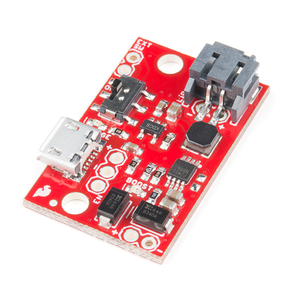
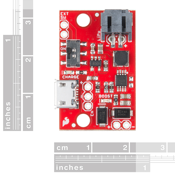
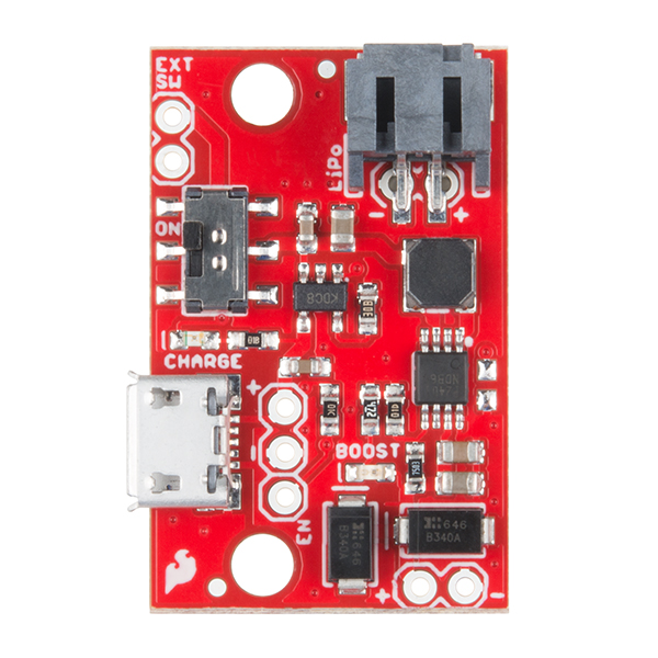
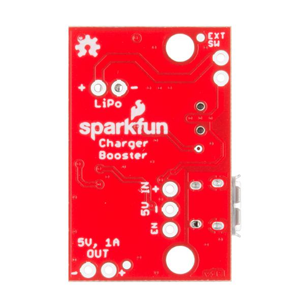
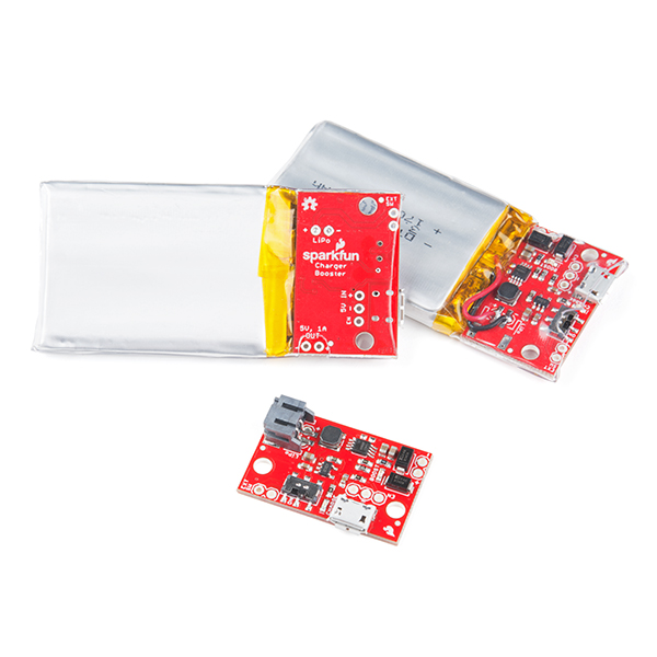
The SparkFun 5V/1A LiPo Charger/Booster is a no-nonsense circuit for generating one amp from a Lithium Polymer battery at 5V. This LiPo charger is a very economical choice that is equipped with a simple booster circuit utilizing the PAM2401 IC, and includes protection diodes so you can run multiple cells in series for an extra kick. While the booster circuit is in operation, this board can draw more current the lower the input voltage, making it perfect to deliver a strong charge in a small amount of time.
The circuit is constructed by feeding an MCP73831 charge controller IC to the LiPo port, and to the input of a PAM2401 boost controller. Multiple connection types are provided for the battery, charge source and switch to allow flexibility of application, and two LEDs provide feedback on system status. If you need more than 5V out of your project, the SparkFun LiPo Charger/Boosters can also be daisy-chained together to get a bigger bang for your buck.
Note: This is not a direct replacement for the SparkFun Power Cell, as it uses a different IC. Also, this board does not possess any undervoltage or other battery protection features, so we do recommend that you use it only with batteries with a built-in protection circuit.
- Charger, microUSB, 500mA
- Booster, 5V, 1A output
- Form factor for our 1,000mAh batteries
- Battery isolation switch with optional external connections
- Enable pin broken out
- Disabled current less than 10uA
- LED indicators for power and charge
- Super-clean output signal (high-frequency switching)
SparkFun LiPo Charger/Booster - 5V/1A Product Help and Resources
Papa Soundie Audio Player Hookup Guide
April 26, 2018
Add sound effects to your project, prop or costume with Papa Soundie Audio Player.
SparkFun 5V/1A LiPo Charger/Booster Hookup Guide
September 28, 2017
This tutorial shows you how to hook up and use the SparkFun 5V/1A LiPo Charger/Booster circuit.
LiPo Fuel Gauge (MAX1704X) Hookup Guide
February 23, 2023
Monitor your LiPo battery with the LiPo fuel gauge! In this tutorial, we will be using the MAX17043 and MAX17048 to monitor a single cell, LiPo battery over the Arduino Serial Monitor. We will also connect a display to view the output without the need to connect the microcontroller to a computer.
Core Skill: Soldering
This skill defines how difficult the soldering is on a particular product. It might be a couple simple solder joints, or require special reflow tools.
Skill Level: Noob - Some basic soldering is required, but it is limited to a just a few pins, basic through-hole soldering, and couple (if any) polarized components. A basic soldering iron is all you should need.
See all skill levels
Core Skill: Electrical Prototyping
If it requires power, you need to know how much, what all the pins do, and how to hook it up. You may need to reference datasheets, schematics, and know the ins and outs of electronics.
Skill Level: Competent - You will be required to reference a datasheet or schematic to know how to use a component. Your knowledge of a datasheet will only require basic features like power requirements, pinouts, or communications type. Also, you may need a power supply that?s greater than 12V or more than 1A worth of current.
See all skill levels
Comments
Looking for answers to technical questions?
We welcome your comments and suggestions below. However, if you are looking for solutions to technical questions please see our Technical Assistance page.
Customer Reviews
4 out of 5
Based on 3 ratings:
1 of 1 found this helpful:
Almost great, but ultimately designed to fail
This little breakout does a lot. Steady 5V/1A output, solid. Elegant battery management, check. Nice shutoff, enable/disable, and configuration features to boot. However, the design simply follows the basic suggested/ typical layout and clearly ignores the application note for the MCP73831/2 Data Sheet on Input Overvoltage Protection (IOVP) -
"Input overvoltage protection must be used when the input power source is hot-pluggable. This includes USB cables and Wall-type power supplies. The cabling of these supplies acts as an inductor. When the supplies are connected/disconnected from the system, large voltage transients are created which may damage the system circuitry. These transients should be snubbed out. A transzorb connected from the V+ input supply connector to the 0V ground reference will snub the transients."
The unit is designed with a uUSB cable. To not expect unregulated/ spikey/ noisy/ non-linear input voltages is simply neglectful. Over time, hot plugging/ unplugging this unit will most likely kill the MCP73831 over time. A simple TVS diode for 10-20 cents would make this a much more stable and reliable design. As is, expect it to fail relatively quick.
Great little circuit
Works as advertised. One comment: Reading the description I expected the "enable" pin would disable the boost, but I found it disables all output. Re-reading the spec, that is what it says. Thus there apparently is no way to disable boost.
It delivers on it's promises
The small size is perfect for a small battery box I built as an alternative to the 4-AA battery power source for a portable sky tracker for astrophotography. The combination of charging and boosting as well as a battery disconnect switch capability without snipping battery leads is a dream come true for small hobby builds. And the red "Power On" LED is night-vision friendly.
Note that the math to calculate your battery capacity might not be simple for your load. This circuit will bend over backwards to meet the power needs of the load in spite of a falling input voltage, which means that the current draw from the battery will increase as time goes on. The worthy LiPo batteries include a low voltage cutoff function to avoid damage by being over drawn. My tracker draws a consistent 50 mA and I was able to get just 16 hours of operation from a 1400 mAH LiPo battery. The simplistic math is 1400/50 = 28 hours. So it would be best to test your project if you need to rely on it for a long running session, and maybe consider selecting a larger battery than the simple math would suggest.
I'm giving it 4 stars: starting with 5 for doing exactly what it says, then taking off 1 for the unavoidable realities of physics that aren't Sparkfun's fault.

I have tested 3 different PCBs with 3 different 10Ahr batteries, all providing a nominal 3.7-3.9V. I have been charging them with 1.2-2A USB wall chargers for most of the day. The charging LED has yet to turn off, but maybe they haven't reached full charge, yet. As soon as I disconnect the micro-USB charger all LEDs turn off and I loose the 5V line. When the battery switch is in the ON position (no charger), the battery terminals sag to < 0.5V and no 5V line from the booster (giving 10mV). With the battery switch in the OFF position, I read the nominal 3.8V on the Li ion battery pack, and expectedly nothing else is powered. I have tried charging for > 6 hours in both the ON and OFF battery switch positions, and still am not getting 5V out once the charger is disconnected. Is there something I am missing? I can power a circuit directly off of the batteries, so I know there is juice. I need the charging and management circuit though, as well as the 5V switcher line.
Hello!! I was using this circuit and everything was working fine. I tested this board by removing the battery and just by connecting through USB cable. A this moment, it is able to make 5v (which was expected), but, when I'm connecting this 5v to any load, the led stop glowing and there is no output at 5v output terminal. So, this board is working only when the battery is connected and we are using a USB cable to charge that but why its not working when we are powering it through USB cable( without the battery connection) and connecting it to the load?? When there is no battery, still we are getting voltage from USB which boost IC is converting to 5v. So, whats the difference when we are powering it through USB or LIPO battery?
Hi there, it sounds like you are looking for technical assistance. Please use the link in the banner above or the steps in the troubleshooting section, to get started with posting a topic in our forums.Our technical support team will do their best to assist you.
That being said, my guess is that the charge that you are pulling is getting supplemented by the battery. Therefore, when you disconnect the battery the USB connection alone (through the charge circuit) can't provide the current draw you need.
Can you hook a solar panel up to the input to charge the battery?
Hello! I would like to add a load sharing circuit to this board in order to use a LiPo battery as a backup battery. I've found this load sharing circuit. Do you see any problems in adding the load sharing circuit (Q1, D1 and R2 in my diagram) before the VIN pin of PAM2401? So that when USB power is applied the VIN pin of PAM2401 will be VUSB - VD1 (drop over D1) and when USB power is off the VIN pin of PAM2401 will be VBAT - VSD (drop over Q1). In both cases, my output (PAM2401 output) would be regulated to 5V. Is that correct? Thanks!
I have a question about this board. While charging a lipo does the board automatically disconnect the arduino from the lipo and power it off of the external power? I've heard that you shouldn't charge a lipo while it is powering a device.
Chris is correct. Pulling the enable pin low disconnects the load from the battery -- I can't remember now but it draws something in the order of microamps during disable.
Alternately, I've found that minimal loads (<10mA) will still allow the battery cycle to complete. So if you can put your device to sleep or disable all of its peripherals, that's probably good enough.
I just read through the "getting started" guide and from that my understanding is "no." There are two options for turning power to the battery off: the battery switch and the "en" pin. Hoping to bump this up as it would be great for the designer to answer the question. I'd like to use this in a simple circuit that can be plugged in to charge. What I'm trying to figure out, as you are, is do we need to instruct the end user to "power off" the device before charging, or can they simply plug it in? Even more specifically: i have a 1Ah LiPo, this, an Esp8266, and a small haptic motor. I'd like to package it up and let people re-charge it. Is that safe? Or, should I turn breakout the battery switch, and have people "turn it off" before plugging in to charge?
This is a pretty basic circuit, I've found that projects I make have a variety of needs so I have to get a bit creative depending on how I want the circuit to operate.
If you want the load to automatically be disconnected, use a small N type mosfet to pull the enable pin low with the gate connected to the USB in rail through a resistor.
If you require the load to stay active (and can tolerate a 0.5v drop) do the above but also put a pair of schottky diodes ORing the USB rail and the output rail to your load. That way the system will redirect power through the supply while pulling the booster offline. If there's too much of a gap in power, build an RC filter on the gate to delay the disconnection.
One project I built has a button wired to turn on the system (microcontroller) when held, and the microcontroller can then power itself off. So in this instance I simply shut the device down before charging. See this Enginursday.
Thanks for the bump
So what is going to happen if I am providing power to the charger over USB while simultaneously drawing 1A from the PAM?
FYI, the babysitter in the post uses high to disable rather than low to disable.
I recently bought this charger and a 1000mAh battery. I charged it with no issues, then used in my setup it until it stopped sending power.
I plugged in a micro usb cable to charge it for 48hrs, and the charge light remained on the whole time. When I plugged it back into my setup, it died within 10 minutes. Do you know what might be going wrong?
I noticed that there's some damage to one of the circuit components: https://imgur.com/s4vPu0P
Could this be causing an issue?
I realized that I got the Ext SW switch and the Enable pin mixed up. I was trying to charge with the battery disconnected! Seems to be working now.
Sounds great! Sorry if it was confusing.
As for that inductor, it shouldn't be chipped like that but it probably won't effect operation -- if the whole top comes off then maybe. It's part of the boost circuit anyway. If it fails you'll have poor (or no) current output capacity but the charger will still work.
Good luck with your project!
Greetings,
I was checking out the PAM2401 spec sheet, and the chip puts out a maximum of 3.0A at 5.0V, if I am not mistaken. The current limit is set by the external resistor, on pin #6 of the chip. If the pin is left floating (which apparently it is on your board, but maybe I cannot see the trace), then the current limit is 3.0A. So I'm wondering why don't you call this a 5-V/3-A charger booster? At any rate, I could use the 3.0A, so if you would kindly point out this resistor R3 so I may remove it, I would be much obliged!
Good question. While the PAM has current limiting capacity through that resistor, the current limiting factor here is actually the inductor (as well as the source's current capacity). Let's say the thing is 100% efficient, 5W out = 5W in. If the output is delivering 1A at 5V, that's 5W power output. If the input is at 2.5V, and 5W is required going in, it needs 2A of input current. The winding of the inductor has resistance which can get in the way of the operation at high currents. See more including some graphs in the hookup guide connecting a load section. All boosters have this property-- the lower the input voltage, the higher the input current.
I designed this such that it can deliver 1A over the entire input voltage range of a LiPo. I actually took my measurements up to 1.3A on the output, but I'd rather provide something with a healthy margin that to call it a 1.3A booster.
Thanks for the fast reply MT, on a holiday no less. The graphs are indeed revealing. I don't know enough about switch-mode regulators to understand fully, but I can appreciate Power In = Power Out (at 100% efficiency). It's nice to know that there is some (substantial) margin above 1A output current. In my application, I am driving LEDs, a motor, and a fairly high wattage camera, so I will have to be careful about coordinating these things. If I had the 3A output, I would not have to worry nearly as much. Thanks again.
I'm using this board to light up 12 LEDs, and even with the charger connected, when I load the circuit the LEDs light up for one second, then turn off. Unfortunately I don't have a multimeter to measure the current, but is this a symptom of an overloaded circuit? What could be going wrong? After this happens, it won't turn on for a while until I charge it, but is connected to a 1000mAh battery, which I don't think is empty
Above it says "includes protection diodes so you can run multiple cells in series for an extra kick". This is misleading and should say multiple charger/boost boards in series instead of cells. The PAM2401 datasheet shows a max input voltage of 4.75V, which is less than 2 lipo cells in series. And the MCP73831 doesn't look like it will charge cells in series. Running cells in series would likely kill the board.
is this available for higher voltage like 6 or 7v?
If not are there any solutions for 6v battery charging?
Meh... Still waiting for a 2-3S Lipo board with 2-5A output at 5V. As mentioned the Adafruit board has been out for a while now and 1A is old news. I have plenty of applications for a 2a+ board that something like this can't be used for. Find me a budget all-in-one $20 -$25 board for 2-5A and I'm in.
Would I be able to shut down the charging circuit using a microcontroller when the temperature gets below freezing, without turning off the load? Or does the charging IC do that automatically?
According to a brief reading into the datasheet it appears to not have this functionality, unless there's something I'm missing.
That's kind of an interesting problem, you want to continue to boost but not charge, all while leaving the charger connected. There's no shutdown pin on the charger IC. I would investigate using a mosfet to switch the charger in and out of the circuit.
Looking for an easy way to adjust the output voltage, although it is not as straightforward as the LiPower.
I tried changing R4 to 688k and 488k just to see if I could get the divider to alter the output, but the output voltage remained the same at 5.1. Is the inductor critical in reducing the boost? I can't say the datasheet or application notes are very helpful.
I am looking for something in the 3.6-4.2V range so I don't have to use another stage of regulator.
The booster is regulating to 0.6V on the feedback pin (FB). Adjust the voltage divider made by R1 and R4 using 0.6 and your desired output voltage as constraints, and it should be OK. I solved R4=600k (with R1=100k) for 4.2V output... maybe there's something else going on here.
The inductor value is not critical to regulation voltage.
Also, R4 is stuffed with 750K from the factory so I'm not sure what's up. I'll let you know if I discover anything.
Keep in mind you can't buck down from a larger battery voltage! The PAM2401 only boosts.
I replaced R4 with a 680k and I'm getting 3.6 volts. Shouldn't I be getting higher than the 4.2 you calculated? Am I doing something wrong?
Thanks for the reply. For the record, I am boosting from a 3.0V lithium primary source. I was completely stumped this morning, so I downloaded the Eagle files. Just noticed that there is an identical 750k (R2) that I thought was R4. Whoops -- wrong resistor! Perhaps R2 isn't too important..since that tiny 750k is long gone anyway. It might be helpful to spin future versions of this board with silkscreen, or at least the voltage divider labeled.
I am loving the 1A boost capability of this chip, excited to see it in action.
Nice product. I can see lots of places I could use it.
A couple of questions about the design. I noticed 2 22uF caps on the output. Is this because 22uF was deemed not sufficient? And by using 3 22uF caps you get a better volume discount than on 1 22uF and 1 47uF?
Also, what is the purpose of the 2 schottky diodes on the output? I get why one (to chain chargers) but why 2?
Thanks!
My main concern when designing this was to make sure the voltage was very noise-free on the output. I can't stand supplies that whine! With that in mind, output capacitance required is a based on the transient load characteristics, which I don't have any control over. a single 22uF may have been fine, but two is better here! And yes, I was considering that less specific components on the board means less work to build, even if it's only a single reel in a machine.
The diodes allow the boards to be used in series -- see the hookup guide for more info. If one goes dead in a chain, the current will be passed by.